43
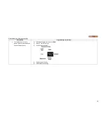
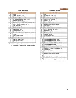
Manual Reset Codes*
#
Description
0
None
1-31
Internal hardware error
47
Flame rod to ground leakage
49
24VAC low/high
64
Fan speed not proved, ignition failure
67
Blocked flue condition
79
Heater Outlet high limit tripped
82
Stack limit tripped (PVC: 149
o
F, CPVC: 194
o
F,
PPE: 230
o
F, SS, AL29-4C: 250
o
F)
91
Inlet sensor fault
92
Outlet sensor fault
93
DHW sensor fault
95
Stack sensor fault
96
Outdoor sensor fault
105
Flame detected out of sequence
106
Flame lost in Main Flame Establishing Period
(MFEP)
107
Flame lost early in run
108
Flame lost in run
109
Ignition failed
112
Pilot test flame timeout
113
Flame circuit timeout
149
Flame detected
* To eliminate the hard lockout error,
1) Press the
button to clear the error on screen
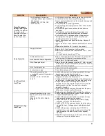
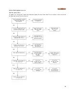
Automatic Reset Codes
#
Description
0
None
29
Burner switch turned OFF
30
Burner switch turned ON
47
Flame rod to ground leakage
49
Abnormal 24Vac voltage
50
Modulation Fault
61
Anti-short Cycle
62
Fan speed not proved
67
Interlock Off, safety circuit is open
69
Pilot test hold
78
Demand lost in run
79
Outlet high limit tripped (internal limit)
81
Delta-T limit exceeded (30
o
F)
91
Inlet sensor fault
92
Outlet sensor fault
93
DHW sensor fault
95
Stack sensor fault
96
Outdoor sensor fault
97-
99
Internal Fault
128
Fan speed failed during prepurge
129
Fan speed failed during preignition
130
Fan speed failed during ignition
131
Fan movement detected during standby
132
Fan speed failed during run
137
Interlock failed to close, safety circuit is open
110
Ignition failure occurred
111
Flame current below threshold (0.8Vdc)
149
Flame detected
150,
291
Flame not detected
301
-
309
Interlock Off, safety circuit is open
460
Interlock off during burn, safety circuit is open
614
Lead boiler was rotated based on measured run
time
Summary of Contents for DynaMax DMH081
Page 2: ......
Page 68: ...65 PART 14 EXPLODED VIEW PARTS LIST DYNAMAX HS WALL HUNG...
Page 69: ...66 DYNAMAX HS FLOOR MOUNT...
Page 76: ...73 PART 15 ELECTRICAL DIAGRAMS 15 1 DM 80 299 INTERNAL WIRING DIAGRAM...
Page 77: ...74 15 2 DM 399 800 INTERNAL WIRING DIAGRAM...
Page 78: ...75...


