4
•
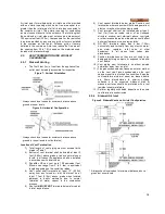
The appliance must be installed so that the ignition
system components are protected from water
(dripping, spraying, etc.) during appliance operation
and
service
(circulator
replacement,
control
replacement, etc.)
•
Appliances located in a residential garage and in
adjacent spaces that open to the garage and are not
part of the living space of a dwelling unit must be
installed so that all burners and burner ignition devices
have a minimum clearance of not less than 18" (46cm)
above the floor. The appliance must be located or
protected so that it is not subject to physical damage
by a moving vehicle.
•
DO NOT install this appliance in any location where
gasoline or flammable vapors are likely to be present.
•
Appliance must be installed on a level floor. Maintain
required clearances from combustible surfaces.
•
The appliance designed for indoor installation (Indoor
Models) must be installed indoors where it is protected
from exposure to wind, rain and weather.
•
The appliance designed for outdoor installation
(Outdoor Models) must be installed outdoors. Always
consider the use of a shelter such as a garden shed in
lieu of direct exposure of the appliance to the
elements. The additional protection afforded by the
shelter will help to minimize nuisance problems with
electrical connections and will allow easier servicing of
the appliance under severe weather conditions.
1.11
CLEARANCE FROM COMBUSTIBLE
MATERIAL
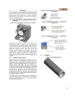
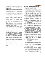
This appliance is suitable for alcove (a closet without a
door) installation with minimum clearances to combustibles
as follows:
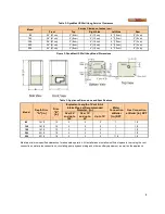
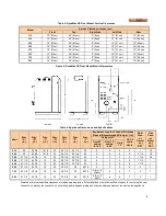
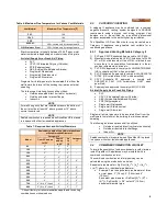
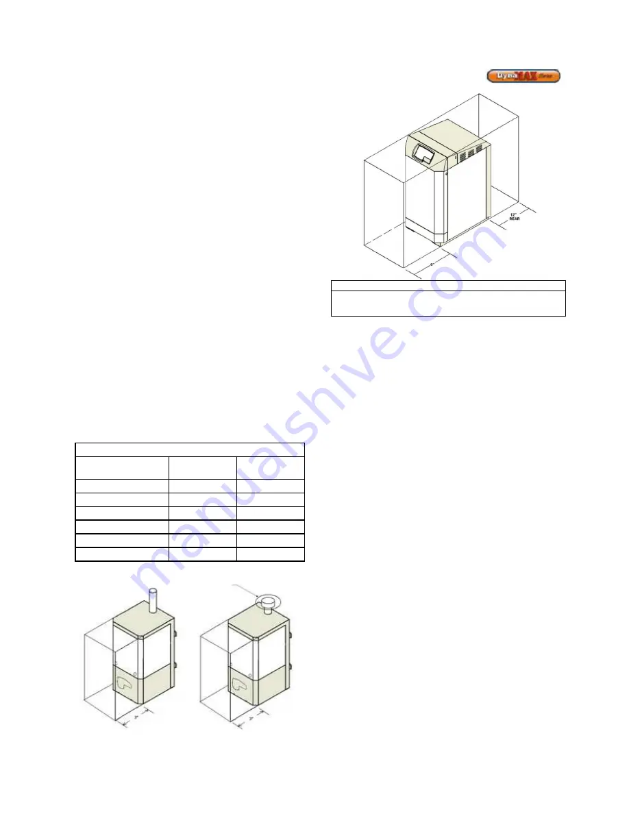
Table 1: Clearance from Combustibles
Clearances from Combustibles
Wall Hung
Model
Floor Mount
Model
TOP:
0”
0"
SIDES:
0”
0"
REAR:
0”
12"
VENT (Vent Adapter):
1”
1"
VENT (PVC/CPVC):
0”
0"
FRONT:
3”
6”
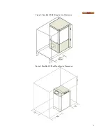
Figure 1: Wall Hung Clearance from Combustibles
Figure 2: Floor Mount Clearance from Combustibles
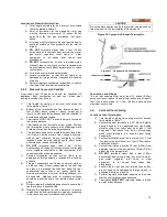
NOTE
Clearances from combustible construction are noted on the
appliance rating plate
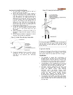
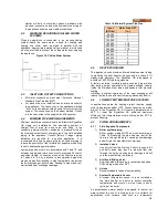
1” From
outer edge
of adapter
PVC/CPVC/PPE Vent Pipe
Single Wall Vent Adapter
Summary of Contents for DynaMax DMH081
Page 2: ......
Page 68: ...65 PART 14 EXPLODED VIEW PARTS LIST DYNAMAX HS WALL HUNG...
Page 69: ...66 DYNAMAX HS FLOOR MOUNT...
Page 76: ...73 PART 15 ELECTRICAL DIAGRAMS 15 1 DM 80 299 INTERNAL WIRING DIAGRAM...
Page 77: ...74 15 2 DM 399 800 INTERNAL WIRING DIAGRAM...
Page 78: ...75...

