Section 06 ELECTRICAL SYSTEM
Subsection 01 (IGNITION SYSTEM)
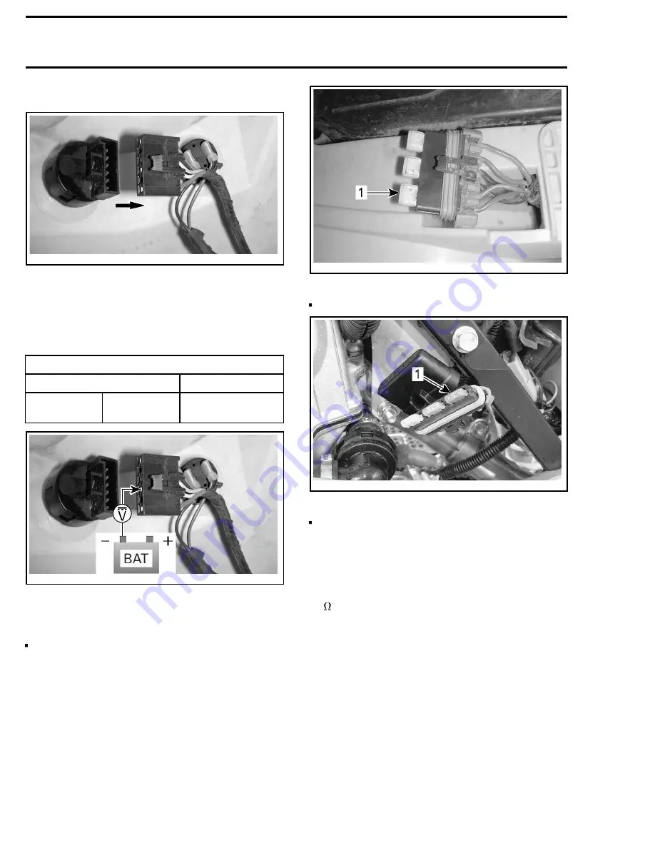
Disconnect the ignition switch connector.
vmr2008-137-001_a
DISCONNECT IGNITION SWITCH
Set the Fluke 115 multimeter (P/N 529 035 868)
to Vdc.
Measure the ignition switch input voltage as fol-
lows.
IGNITIONS WITCH INPUT VOLTAGE TEST
TEST PROBES
VOLTAGE
Pin C
(BEIGE wire)
Battery
ground
Battery voltage
vmr2008-137-001_b
IGNITION SWITCH INPUT VOLTAGE TEST
If you do not obtain battery voltage, test the fol-
lowing:
20 A main fuse
vmr2008-026-001_a
1. 20 A main fuse
5 A ECM fuse
vmr2008-026-002_a
1. 5 A ECM fuse
Wiring harness.
If the ignition switch input voltage is good, carry
out an ignition switch continuity test.
Ignition Switch Continuity Test
Set the Fluke 115 multimeter (P/N 529 035 868)
to
.
Measure the resistance through the ignition
switch between the following pins.
NOTE:
Connector pin B is not used.
228
vmr2008-024
Summary of Contents for DS 450 2008
Page 1: ...2008 Shop Manual DS 450 DS 450 X ...
Page 20: ......
Page 24: ......
Page 26: ......
Page 30: ......
Page 36: ......
Page 70: ......
Page 86: ......
Page 104: ......
Page 134: ......
Page 186: ......
Page 190: ......
Page 198: ......
Page 244: ......
Page 290: ......
Page 310: ......
Page 324: ......
Page 336: ......
Page 348: ......
Page 370: ......
Page 382: ......
Page 388: ......
Page 396: ......
Page 398: ......
Page 399: ...NOTES ...
Page 400: ...NOTES ...


