background image

MAINTENANCE PROCEDURES

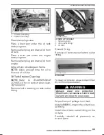
NOTICE

Take care not to damage

O-ring while inserting outlet fitting
into oil tank. Apply oil on O-ring to
ease installation.

vmo2008-011-100_a

OIL OUTLET ASSEMBLY

1. Hexagonal bolt
2. Washer
3. Insert
4. Outlet fitting
5. O-ring
6. Strainer

Oil Filter Replacement

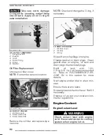
Unscrew oil filter cover.

NOTE:

Remember screws location.

vmo2008-011-042_a

LH SIDE OF ENGINE

1. Oil filter cover
2. Screw (M6 x 25)
3. Screw (M6 x 55)

Remove the oil filter and replace by a
new one.

NOTE:

Check and change the O-ring, if

necessary.

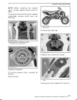
vmo2008-011-084_a

LH SIDE OF ENGINE

1. Oil filter cover
2. Oil filter
3. O-ring

Wipe off any oil spillage on engine.

Change gasket on drain plugs. Clean
gasket area on engine, oil tank and
drain plugs then reinstall plugs.

Refill

oil

tank

with

1.8 L

(1.9 qt (U.S. liq.)) of the recommended
oil. Refer to

RECOMMENDED EN-

GINE OIL

in this section for more

details.

Start engine and let idle for a few min-
utes.

Ensure there are no leaks.

Stop engine and check oil level. Refill if
necessary.

Dispose oil as per your local environ-
mental regulations.

Engine Coolant

Engine Coolant Level

WARNING

Check coolant level with engine
cold. Never add coolant in cooling
system when engine is hot.

90

______________

Summary of Contents for DS 450 Series

Page 1: ... important safety information Minimum recommended operator s age 16 years old Experienced operator only Keep this Operator s Guide in the vehicle WARNING DS 450TM Series DS 450TM 2 1 9 0 0 0 7 8 0 Series Includes Safety Vehicle and Maintenance Information Operator s Guide 2012 ...

Page 2: ...injury including the possibility of death WARNING This vehicle may exceed the performance of other vehicles you may have ridden in the past Take time to familiarize yourself with your new vehicle CALIFORNIA PROPOSITION 65 WARNING WARNING This product contains or emits chemicals known to the state of California to cause cancer and birth defects or other reproductive harm In Canada products are dist...

Page 3: ...ocal authorities for avail ability in your area Failure to follow the warnings con tained in this Operator s Guide can result in SERIOUS INJURY or DEATH Safety Messages The types of safety messages what they look like and how they are used in this guide are explained as follows WARNING Indicates a potential hazard if not avoided could result in serious in jury or death CAUTION Indicates a hazard s...

Page 4: ...n this guide may occur BRP reserves the right at any time to discontinue or change specifications designs fea tures models or equipment without incurring any obligation upon itself This Operator s Guide and the SAFETY DVD should remain with the vehicle when it s sold While reading this Operator s Guide remember that WARNING Indicates a potential hazard that if not avoided could result in serious i...

Page 5: ... Inspection 38 Clothing 39 Carrying Passenger 40 Carrying Loads 40 Recreational Riding 40 Environment 41 Design Limitation 41 Off Highway Operation 42 General Operating and Safety Precautions 42 Riding Techniques 44 IMPORTANT ON PRODUCT LABELS 50 Hang Tag 50 Vehicle Safety Labels 50 Compliance Labels 53 Technical Information Label 54 VEHICLE INFORMATION CONTROLS INSTRUMENT EQUIPMENTS 56 1 Throttle...

Page 6: ...Toe 70 Rear Track Width Adjustment X xc and X mx 71 Caster Adjustment X xc and X mx 72 Camber Adjustment X mx 74 Suspension Adjustments Guideline 75 Front Suspension Adjustments 75 Rear Suspension Adjustments 77 Front Suspension Factory Settings 79 Rear Suspension Factory Settings 79 VEHICLE TRANSPORTATION 80 MAINTENANCE INFORMATION 5 HOUR AND 10 HOUR INITIAL SERVICES 82 5 Hour Engine Oil and Filt...

Page 7: ...ame 116 VEHICLE CARE 117 Post Operation Care 117 Vehicle Cleaning and Protection 117 STORAGE AND PRESEASON PREPARATION 118 TECHNICAL INFORMATION VEHICLE IDENTIFICATION 120 Vehicle Identification Number 120 Engine Identification Number 120 NOISE EMISSION CONTROL SYSTEM REGULATION 121 USA and Canada Only 121 SPECIFICATIONS 122 TROUBLESHOOTING TROUBLESHOOTING GUIDELINES 130 WARRANTY BRP LIMITED WARRA...

Page 8: ...OF CONTENTS BRP LIMITED WARRANTY FOR THE EUROPEAN AND THE RUSSIAN ECONOMIC AREAS AND TURKEY 2012 CAN AMTM ATV 145 CUSTOMER INFORMATION PRIVACY INFORMATION 152 CHANGE OF ADDRESS OWNERSHIP 153 6 _______________ ...

Page 9: ...SAFETY INFORMATION ________ SAFETY INFORMATION ________ 7 ...

Page 10: ...building through openings such as windows and doors Avoid Gasoline Fires and Other Hazards Gasoline is extremely flammable and highly explosive Fuel vapors can spread and be ignited by a spark or flame many feet away from the en gine To reduce the risk of fire or explo sion follow these instructions Never start or operate the engine with the fuel cap removed Use only an approved red gasoline conta...

Page 11: ...hat fits properly You should also wear eye protection goggles or face shield gloves boots long sleeved shirt or jacket and long pants Never ride this vehicle under the influence of alcohol or drugs They slow reac tion time and impair judgement Never operate at excessive speeds Always go at a speed that is proper for the terrain visibility and operating conditions and your experience Never attempt ...

Page 12: ...s Guide on level ground Avoid crossing the side of a steep hill if possible Always use proper procedures if you stall or roll backwards when climbing a hill To avoid stalling use proper gear and maintain a steady speed when climbing a hill If you stall or roll backwards follow the special procedure for braking described in this Operator s Guide Dismount on the uphill side or to a side if pointed s...

Page 13: ...ing course All operators should receive training from a certified instructor FOR MORE INFORMATION ABOUT ATV SAFETY contact an authorized Can Am dealer to find out about available training courses nearest you USA and Canada only call the Specialty Vehicle Institute of America SVIA at 1 800 887 2887 or in Canada the Canada Safety Council CSC at 1 613 739 1535 ________ SAFETY INFORMATION ________ 11 ...

Page 14: ...er instruction WHAT CAN HAPPEN The risk of an accident is greatly increased if the operator does not know how to operate this vehicle properly in different situations and on different types of terrain HOW TO AVOID THE HAZARD Beginning and inexperienced operators should complete a training course They should then regularly practice the skills learned in the course and the operating techniques descr...

Page 15: ...n can lead to severe injury or death of the child Even though a child may be within the age group for which this vehicle is recommended he may not have the skills abilities or judgment needed to operate this vehicle safely and may be involved in a serious accident HOW TO AVOID THE HAZARD No one under 16 should operate this vehicle ________ SAFETY INFORMATION ________ 13 ...

Page 16: ...ur ability to balance and control this vehicle Could cause an accident resulting in harm to you and or your passenger HOW TO AVOID THE HAZARD Never carry a passenger Even with a long seat that provides unrestricted operator movement it is not designed nor intended to carry passenger s 14 _______ SAFETY INFORMATION ________ ...

Page 17: ...for off road use only not for use on pavement Paved surfaces may seriously affect handling and control of this vehicle and may cause the vehicle to go out of control HOW TO AVOID THE HAZARD Never operate this vehicle on any paved surfaces including sidewalks driveways parking lots and streets ________ SAFETY INFORMATION ________ 15 ...

Page 18: ...ys WHAT CAN HAPPEN You can collide with another vehicle HOW TO AVOID THE HAZARD Never operate this vehicle on any public street road or highway even a dirt or gravel one In many states or provinces it is illegal to operate this vehicle on public streets roads or highways 16 _______ SAFETY INFORMATION ________ ...

Page 19: ...death in the event of an accident Riding without eye protection can result in an accident and increases the chances of a severe injury in the event of an accident Riding without protective clothing increases the chances of severe injury in the event of an accident HOW TO AVOID THE HAZARD Always wear an approved helmet that fits properly You should also wear Eye protection goggles or face shield Gl...

Page 20: ...rugs WHAT CAN HAPPEN Could seriously affect your judgment Could cause you to react more slowly Could affect your balance and perception Could result in an accident or death HOW TO AVOID THE HAZARD Never consume alcohol or drugs before or while riding this vehicle 18 _______ SAFETY INFORMATION ________ ...

Page 21: ... speeds WHAT CAN HAPPEN Increases your chances of losing control of the vehicle which can result in an accident HOW TO AVOID THE HAZARD Always travel at a speed which is proper for the terrain visibility and oper ating conditions and your experience ________ SAFETY INFORMATION ________ 19 ...

Page 22: ... POTENTIAL HAZARD Failure to inspect the vehicle before operating Failure to properly maintain the vehicle WHAT CAN HAPPEN Increases the possibility of an accident or equipment damage HOW TO AVOID THE HAZARD Always inspect your vehicle every time prior to use it to make sure the vehi cle is in safe operating condition Always follow the inspection and maintenance procedures and schedules described ...

Page 23: ...ARNING V00A0BQ POTENTIAL HAZARD Removing hands from handlebar or feet from the footrests during opera tion WHAT CAN HAPPEN Removing even one hand or foot can reduce your ability to control the vehi cle or could cause you to lose your balance and fall off the vehicle If you re move a foot from the footrests your foot or leg may come into contact with the rear wheels which could injure you or cause ...

Page 24: ...PEN You can come upon hidden rocks bumps or holes without enough time to react Could result in the vehicle overturning or loss of control HOW TO AVOID THE HAZARD Go slowly and be extra careful when operating on unfamiliar terrain Always be alert to changing terrain conditions when operating the vehicle 22 _______ SAFETY INFORMATION ________ ...

Page 25: ...oss of traction or vehicle control which could result in an acci dent including an overturn HOW TO AVOID THE HAZARD Do not operate on excessively rough slippery or loose terrain until you have learned and practiced the skills necessary to control this vehicle on such terrain Always be especially cautious on these kinds of terrain ________ SAFETY INFORMATION ________ 23 ...

Page 26: ...out of control causing a collision or overturn HOW TO AVOID THE HAZARD Always follow proper procedures for turning as described further in this Op erator s Guide Practice turning at low speeds before attempting to turn at faster speeds Do not turn at excessive speed 24 _______ SAFETY INFORMATION ________ ...

Page 27: ...The vehicle can overturn more easily on extremely steep hills than on level surfaces or small hills HOW TO AVOID THE HAZARD Never operate this vehicle on hills too steep for the vehicle or for your abili ties Practice on smaller hills before attempting larger hills ________ SAFETY INFORMATION ________ 25 ...

Page 28: ...his Operator s Guide Always check the terrain carefully before you start up any hill Never climb hills with excessively slippery or loose surfaces Shift your weight forward Never open the throttle suddenly or make sudden gear changes The vehi cle could flip over backwards Never go over the top of any hill at high speed An obstacle a sharp drop or another vehicle or person could be on the other sid...

Page 29: ...hills as described further in this Operator s Guide NOTE A special technique is required when braking as you go down a hill Always check the terrain carefully before you start down any hill Shift your weight backward Never go down a hill at high speed Avoid going down a hill at an angle which would cause the vehicle to lean sharply to one side Go straight down the hill where possible ________ SAFE...

Page 30: ...l you have mastered the turning technique as described further in this Operator s Guide on level ground Be very careful when turning on any hill Avoid crossing the side of a steep hill if possible When crossing the side of a hill Always follow proper procedures as described further in this Operator s Guide Avoid hills with excessively slippery or loose surfaces Shift your weight to the uphill side...

Page 31: ...the brakes Lock parking brake after you have stopped Dismount on uphill side or to a side if pointed straight uphill If you begin rolling backwards Keep your weight uphill Never open the throttle suddenly or make sudden gear changes The vehicle could flip over backwards Never apply the rear brake while rolling backwards Apply the front brake gradually When fully stopped apply rear brake as well an...

Page 32: ...llision Could cause the vehicle to overturn HOW TO AVOID THE HAZARD Before operating in a new area check for obstacles Never attempt to ride over large obstacles such as large rocks or fallen trees When you go over obstacles always follow proper procedures as described further in this Operator s Guide 30 _______ SAFETY INFORMATION ________ ...

Page 33: ...ion unexpectedly which may cause the vehicle to overturn HOW TO AVOID THE HAZARD Learn to safely control skidding or sliding by practicing at low speeds and on level smooth terrain On extremely slippery surfaces such as ice go slowly and be very cautious in order to reduce the chance of skidding or sliding out of control ________ SAFETY INFORMATION ________ 31 ...

Page 34: ...HAZARD Never operate this vehicle in fast flowing water or in water deeper than that specified further in this Operator s Guide Check water depth and current before you attempt to cross any water Wa ter should not go above footrests Remember that wet brakes may have reduced stopping ability Test your brakes after leaving water If necessary apply them several times to let friction dry out the pads ...

Page 35: ...per or uneven tire pressure may cause loss of control tire blow outs tire to move around on its rim and increases the risk of an accident HOW TO AVOID THE HAZARD Always use the size and type of tires specified further in this Operator s Guide for this vehicle Always maintain proper tire pressure as described further in this Operator s Guide Always replace wheels or tires that are damaged ________ ...

Page 36: ...h improper installation or use of acces sories All parts and accessories added to this vehicle should be approved by BRP and should be installed and used according to instructions If you have questions consult an authorized Can Am dealer Modification of the vehicle to increase speed and performance may violate the terms and conditions of your vehicle s limited warranty In addition cer tain modific...

Page 37: ...n accident HOW TO AVOID THE HAZARD Never exceed the stated load capacity for this vehicle including operator as well as other loads and added accessories Cargo should be properly distributed and securely attached Reduce speed when carrying cargo Allow greater distance for braking Always follow the instructions in this Operator s Guide for carrying cargo ________ SAFETY INFORMATION ________ 35 ...

Page 38: ...AL HAZARD Transporting flammable or dangerous material can lead to explosions WHAT CAN HAPPEN This can cause serious injury or death HOW TO AVOID THE HAZARD Never transport flammable or dangerous material 36 _______ SAFETY INFORMATION ________ ...

Page 39: ...itive or physical impairments or who are high risk takers have an increased exposure to overturns or collisions which may result in injury including death Not all vehicles are the same Each has its own unique performance characteris tics controls and features Each will ride and handle differently Become completely familiar with the operational controls and the general opera tion of the vehicle bef...

Page 40: ...mes to ensure it operates freely It must return to idle position when released Activate the brake lever and brake pedal to make sure the brakes fully apply They must fully return when released Ensure front brake lever position is adjusted to suit drivers hand Check all brake line fittings for tightness and against leaks With parking brake correctly applied activate the clutch lever It must fully r...

Page 41: ...the operator always wears the appropriate protective clothing and apparel including an approved helmet eye protection boots gloves a long sleeved shirt and pants This type of clothing will provide you protection from some of the minor hazards you may encounter en route The operator must never wear loose clothing such as a scarf that may get entangled in the vehicle or on tree branches and shrubs D...

Page 42: ...ntended to carry passenger s Carrying passenger s may affect the stability and your control of the vehicle Carrying Loads Never load cargo on this vehicle Recreational Riding Respect the rights and limitations of others Stay away from areas designated for other types of off road use This includes snowmobile trails equestrian trails cross country ski trails mountain bike trails etc Never assume the...

Page 43: ...the beaten path away from most communities However you should always respect nature and the rights of others to enjoy it Do not ride in environmentally sensitive areas Do not drive over forest crops or shrubs nor cut down trees or take down fencing nor spin your wheels and destroy the terrain Tread Lightly Chasing wildlife is in many areas illegal Wildlife can die of exhaustion after being chased ...

Page 44: ...rmit Constantly watch the terrain ahead for sudden changes in slopes or obstacles such as rocks or stumps that may cause loss of stability resulting in tip over or rollover Never operate the vehicle if the controls do not function normally When stopped or parked always apply the parking brake This is especially impor tant when parking on a slope On very steep inclines or if the vehicle is carrying...

Page 45: ...lation openings block the radiator and fan and interfere with the movement of control levers switches and brake pedal Before starting with your ATV check the steering throttle and brake lever and pedal controls for interference free operation Whenever an ATV is ridden on a snow covered drive path the tire grip is generally reduced causing the vehicle to react differently to control inputs from the...

Page 46: ...or tipover To maximize comfort and avoid frostbite always wear clothing and ATV protective equipment appropriate for the weather conditions you will be exposed to during your ride At the end of each ride it is a good practice to clean the vehicle body and all moving components brakes steering components drivelines controls radiator fan etc from any snow or ice accumulations Wet snow will turn to i...

Page 47: ...e reasons pavement may seriously affect the handling and control of the vehicle Riding on roads or soft shoulders may confuse other road users especially if your lights are on If you have to cross a road the lead driver should get off his vehicle then observe and give directions to the other riders The last person after crossing then assists the lead driver to cross Do not travel on sidewalks They...

Page 48: ...icle Avoid rapid braking This again will possibly result in an uncontrolled slide and tip over of the vehicle Slush should be avoided at all times since it could block the operation or controls of the vehicle Riding in snow may affect the brakes stopping ability Safely reduce speed and allow greater distance for braking Snow projection may cause ice build up or snow accumulation on brake component...

Page 49: ... and follow all posted trail signs They are there to help you and others Obstacles in the trail should be traversed with caution This includes loose rocks fallen trees slippery surfaces fences posts and embankments and depressions You should avoid them whenever possible Remember that some obstacles are too large or dangerous to cross and should be avoided Small rocks or fallen trees may be safely ...

Page 50: ...ful not to slide Put the parking brake dismount then remove the parking brake while maintaining brakes applied Then use the U turn or K turn while walking back next to the vehicle on the up hill side and with a hand on the brake lever slowly back the rear of the vehicle toward the top of the hill then drive downhill Always walk or dismount on the upside of the slope while keeping clear of the vehi...

Page 51: ...o however it is important that you ALWAYS keep your body weight on the upside of the slope and be prepared to dismount on that side should the vehicle begin to topple Do not try to stop or save the vehicle from damage V00A0ZL While reading this Operator s Guide remember that WARNING Indicates a potential hazard that if not avoided could result in serious injury or death ________ SAFETY INFORMATION...

Page 52: ...mo2009 005 003_en 704901107 vmo2006 005 009_en Vehicle Safety Labels The following labels are on your vehicle and they should be considered perma nent parts of the vehicle If missing or damaged they can be replaced free of charge See an authorized Can Am dealer NOTE The following illustrations used in this Operator s Guide are a general representation only Your model may differ 50 _______ SAFETY I...

Page 53: ...IMPORTANT ON PRODUCT LABELS vmo2008 011 021_a vmo2008 011 022_a vmo2008 011 098_b vmo2008 011 023_a vmo2008 011 061_b UNDERNEATH ACCESS COVER vmo2008 011 025_a ________ SAFETY INFORMATION ________ 51 ...

Page 54: ...imum It could cause the tire to disloge from the rim NEVER exceed the vehicle load capacity of 100 kg 220 lb Including weight of operator and accessories Improper tire pressure or overloading can cause loss of control resulting in SEVERE INJURY or DEATH COLD TIRE PRESSURE LOAD FRONT UP TO 100 kg 220 lb REAR MAX 48 3 kPa 7 PSI MIN 34 5 kPa 5 PSI MAX 48 3 kPa 9 PSI MIN 34 5 kPa 7 PSI 704901365 LABEL...

Page 55: ...8 9 kPa 10 PSI MIN 55 2 kPa 8 PSI MAX 62 1 kPa 9 PSI MIN 48 3 kPa 7 PSI 704902001 LABEL 6 DS 450 X MX vmo2010 010 100_a LABEL 7 vmo2008 011 090 LABEL 8 Compliance Labels 704902867 LOCATED ON LEFT SIDE MEMBER OF FRAME THIS VEHICLE IS AN ALL TERRAIN VEHICLE AND IS NOT INTENDED FOR USE ON PUBLIC ROADS POWER PUISSANCE POIDS EN ETAT DE MARCHE WET WEIGHT kW kg CE VEHICULE EST UN VEHICULE TOUT TERRAIN QU...

Page 56: ...WELL ADJUSTED AND LUBRIC ATED FREE PL AY IS xx mm x x WITH DRIVER ON VEHICLE SEE OWNERS MANUAL FOR COMPLETE INSTRUCTIONS xx mm x x vmo2008 011 088_en While reading this Operator s Guide remember that WARNING Indicates a potential hazard that if not avoided could result in serious injury or death 54 _______ SAFETY INFORMATION ________ ...

Page 57: ...VEHICLE INFORMATION _______________ 55 ...

Page 58: ...UIPMENTS 10 8 1 7 6 3 5 9 11 2 4 vmo2009 005 002_c TYPICAL While reading this Operator s Guide remember that WARNING Indicates a potential hazard that if not avoided could result in serious injury or death 56 ______________ ...

Page 59: ...s 2 Front Brake Lever The front brake lever is located on the RH side of the handlebar When compressed the front brakes are applied When released it should automatically return to its original po sition Braking effect is proportional to the force applied on the lever and to the type and condition of the terrain vmo2008 011 002_a 1 Brake lever 2 To apply brake Front Brake Lever Adjustment The brake...

Page 60: ... brake needs to be locked for exam ple such as doing a K turn during trans portation or when the vehicle is not in operation vmo2008 011 005_a 1 Parking brake WARNING Always use the parking brake when the vehicle is not in opera tion WARNING Make sure parking brake is fully disengaged before operating the vehicle When you ride the vehicle brakes that are caused to drag by a con tinuous pressure on...

Page 61: ...to its original posi tion Front brake lever should return to rest position Always release parking brake before riding 5 Multifunction Switch The multifunction switch is located on the LH side of the handlebar The controls located on this multifunc tion switch housing are vmo2008 011 007_a 1 Headlights switch 2 Emergency engine stop switch 3 Engine start button Headlights Switch vmo2008 011 008_a H...

Page 62: ...ne stop switch 2 OFF 3 RUN Engine Start Button The start button is used to start the en gine When the start button is pushed the starter motor will crank the engine Refer to STARTING THE ENGINE in OPERATING INSTRUCTIONS section for proper starting procedure vmo2008 011 009_b 1 Engine start button 6 Ignition Switch The ignition switch is located on the left side of the vehicle on top of the body pa...

Page 63: ...evel There is approximately 2 5 L 0 6 U S gal of fuel left in fuel tank 1 The lamp stays ON when the ignition switch key and emergency engine stop switch are in running position and the engine is not running 8 Rear Brake Pedal The rear brake pedal is located on the RH side of the vehicle in front of the footpeg When pressed down the rear brake is applied When released it should return to its origi...

Page 64: ... Seat Removal Pull latch rearward while gently lifting rear of seat Continue lifting move ment until you can release seat retain ing devices then completely remove seat vmo2008 011 030_a 1 Seat latch Seat Installation Insert seat front upper slot into coolant tank hook then make sure seat middle tab is well engaged When seat rests in its position firmly push seat down to latch NOTE A distinctive s...

Page 65: ...CONTROLS INSTRUMENT EQUIPMENTS WARNING Make sure seat is securely latched before riding _______________ 63 ...

Page 66: ...ondi tion is noticed whistling sound heard when loosening fuel tank cap have vehicle inspected and or repaired before further operation Fuel is flammable and explosive under certain conditions Never use an open flame to check fuel level Never smoke or allow flame or spark in vicinity Always work in a well ventilated area Never top up the fuel tank be fore placing the vehicle in a warm area As temp...

Page 67: ...el reaches the bottom of filler neck Do not overfill 7 Fully tighten fuel tank cap clock wise 8 Position vent tube in steering col umn vmo2008 011 106_a 1 Fuel tank cap 2 Vent tube While reading this Operator s Guide remember that WARNING Indicates a potential hazard that if not avoided could result in serious injury or death _______________ 65 ...

Page 68: ...de open throt tle accelerations prolonged cruising speeds and engine overheating are detrimental during the break in period Starting the Engine Insert key in ignition switch and turn to ON position vmo2008 011 027_b Place the emergency engine stop switch to RUN position vmo2008 011 038_a Shift transmission to NEUTRAL posi tion or press and hold clutch lever vmo2008 011 019_c vmo2008 011 004_b Pres...

Page 69: ...atically return to its original position To upshift to a higher gear put the end of your boot under gearshift lever and lift up the pedal one full stroke To downshift lean the tip of the gearshift pedal and depress pedal one full stroke vmo2008 011 019_g WARNING Always release the throttle when shifting gears Shifting gears with out releasing the throttle could cause loss of control or cause the v...

Page 70: ..._a Depress and hold clutch lever vmo2008 011 004_b Shift to 1st gear WARNING Always use the clutch lever when shifting gears vmo2008 011 019_d Set the emergency engine stop switch to OFF position vmo2008 011 009_c Turn ignition key to OFF position and re move key 68 ______________ ...

Page 71: ...nd air filter housing Check engine oil level and refill if necessary Check engine coolant level and refill if necessary What to Do if Vehicle Is Immersed in Water Should the vehicle become immersed it will be necessary to take it to an au thorized Can Am dealer as soon as pos sible NEVER START THE ENGINE NOTICE Immersion of the vehi cle can cause serious damage if the correct restart procedure is ...

Page 72: ...it is in straight ahead position by measur ing from the extremities of the han dlebar to a rear fixed point vmr2008 029 045_a A Same length NOTE The reference point must be the same to each side 3 Tie handlebar to prevent move ments during alignment 4 Measure the distance between front wheels center to center vmr2008 029 043_a A Front distance B Rear distance vmr2008 029 044_a C Same height Refer ...

Page 73: ... PROCEDURES section 2 Remove and discard the cotter pin 3 Unscrew the rear wheel hub nut us ing a 41 mm socket and a pry bar as shown vmr2008 028 020_a 1 41 mm socket 2 Pry bar 4 Adjust track width by putting the de sired amount of spacers between rear axle flange and wheel hub in ner side of wheel hub Refer to the TRACK WIDTH SPACER AR RANGEMENT table below to prop erly adjust track width 5 Apply...

Page 74: ...cm 47 in 2 2 122 cm 48 in 3 1 124 5 cm 49 in 4 0 127 cm 50 in Caster Adjustment X xc and X mx The caster angle is the angle between the vertical and the steering knuckle pivot axis in a the longitudinal axis A higher caster angle improves direc tional stability but increases steering effort For best controls in bumpy trails select a high caster angle A lower caster angle gives a quicker steering r...

Page 75: ...from side to side of the upper sus pension arm bearing housings Re fer to the following illustration and the CASTER ADJUSTMENT GUIDE below Keep the total amount of shims across each bearing housing NOTE Always move the same amount of shims in front or behind both of the upper suspension arm bearing housings Use the following illustra tion and table to place shims correctly in all four positions ac...

Page 76: ...n arm 2 Ball joint assembly 3 Lock nut 4 Retaining nut 5 Mounting sleeve NOTE The caster camber and steer ing alignment toe are interrelated Start from the factory settings and customize each adjustment one at a time Correct the other adjustments if needed To adjust the camber angle proceed as follows on each side 1 Support vehicle securely using jack stands 2 Loosen the lock nut several turns the...

Page 77: ... adjustments vary with driver s weight personal preference riding speed and field con dition Starting from the factory settings cus tomize each adjustment one at a time Front and rear adjustments are interre lated It may be necessary to readjust the rear shock absorber after adjust ing front shock absorbers for instance Test run the vehicle under the same conditions trail speed driver riding posit...

Page 78: ...just it vmo2008 021 004_a 1 Low speed compression adjuster flat screwdriver Turning it clockwise H increases shock damping action stiffer Turning it counterclockwise S de creases shock damping action softer High Speed Compression Damping X xc and X mx Use a 17 mm wrench to adjust it vmo2008 021 004_b TYPICAL X XC AND X MX 1 High speed compression adjuster 17 mm wrench Turning it clockwise H increa...

Page 79: ...MENT Step 1 Loosen top locking ring Step 2 Turn adjusting ring accordingly Step 3 Tighten top locking ring Lift the rear of the vehicle Spring length should be measured without load on the wheels vmo2008 011 079_a TYPICAL A Spring length Low Speed Compression Damping Use a flat screwdriver to adjust it vmo2008 011 060_a TYPICAL DS 450 DS 450 X XC 1 Low speed compression adjuster flat screwdriver N...

Page 80: ...located on the RH side near the rear brake fluid reservoir On the X mx model the adjuster is located at rear beneath the RH fender vmo2009 010 002_a DS 450 X MX SHOWN 1 High speed compression adjuster 17 mm wrench Turning it clockwise H increases shock damping action stiffer Turning it counterclockwise S de creases shock damping action softer Rebound Damping Use a flat screwdriver to adjust it vmo...

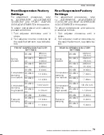
Page 81: ...eed DS 450 X mx 1 1 2 turn DS 450 9 clicks DS 450 X xc 12 clicks Rebound damping DS 450 X mx 11 clicks Rear Suspension Factory Settings For adjustment procedures refer to SUSPENSION ADJUSTMENTS GUIDELINE and REAR SUSPENSION ADJUSTMENTS in this section To adjust compression and rebound proceed as follows 1 Turn adjuster clockwise until it stops 2 Turn adjuster counter clockwise by the specified amo...

Page 82: ... be in its normal operating position on all 4 wheels V00A17Y Remember to Apply the parking brake and place the transmission in 1st gear Secure the vehicle using the appro priate areas See the following illus tration NOTICE Attaching vehicle at other locations may damage the vehicle vmo2008 011 039_a TYPICAL DS 450 FRONT LOCATION vmo2008 018 017_a TYPICAL DS 450 X XC X MX FRONT LOCATION vmo2008 011...

Page 83: ...MAINTENANCE INFORMATION _______________ 81 ...

Page 84: ...ng whichever comes first Contact an authorized Can Am dealer for more details Initial Inspection We suggest that after the first 10 hours or 400 km 250 mi of operation whichever comes first your vehicle be inspected by an authorized Can Am dealer This in spection is very important and must not be neglected Refer to the MAINTENANCE SCHEDULE for the details of the initial inspection NOTE The initial...

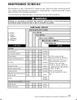
Page 85: ...I Inspect L Lubricate R Replace To be performed by PART TASK LEGEND ENGINE Oil and filter 1 R Customer Oil reservoir strainer C Customer Engine valves I A I A Dealer Engine mounting fasteners I I Dealer Air filter I C L 2 R 2 Customer Exhaust system I I Dealer Muffler spark arrester C Customer Engine coolant I I 3 R Customer Radiator cap cooling system pressure test I I Dealer Clutch 4 Dealer Cust...

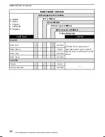
Page 86: ...Customer ECM connectors visual inspection without disconnecting I Dealer Electrical connections and fastening ignition system starting system fuel injectors etc I I Dealer Emergency engine stop switch I I Customer Lighting system headlights and taillight I I Customer 5 Apply HEAT SINK PASTE P12 P N 420 897 186 on spark plugs threads before installation DRIVE SYSTEM Drive chain and slider 6 Custome...

Page 87: ...teners I I Dealer Steering column and bearing 7 I I Dealer Tie rod ends I I Customer Front wheel alignment I A I A Dealer 7 More often under severe use such dusty as area sand snow wet or muddy conditions REAR SUSPENSION Swing arm I I L Dealer Suspension linkage I L I L Dealer Customer Shock absorber I Customer Shock absorber lower pivot L Dealer FRONT SUSPENSION Suspension arms I I L Customer Bal...

Page 88: ...A Adjust C Clean I Inspect L Lubricate R Replace To be performed by PART TASK LEGEND BRAKES Brake fluid I I R 10 Customer Brake pads 9 I Dealer Brake discs I Customer Brake hoses I Customer 9 Brake fluid replacement or any brake system repairs must be performed by an authorized Can Am dealer CHASSIS Chassis I Dealer Chassis fasteners I I Customer 86 ______________ ...

Page 89: ...il Engine Oil Level The engine oil tank is located in front of engine NOTICE Check level frequently and refill if necessary Do not over fill Operating the engine with an improper level may severely dam age engine transmission Wipe off any spillage NOTE While checking the oil level vi sually inspect oil tank and engine area for leaks vmo2008 011 014_a LH SIDE OF VEHICLE 1 Oil tank dipstick With veh...

Page 90: ...ives in Can Am ATV wet clutch equipped vehicles There is no known equivalent on the mar ket for the moment If a high quality equivalent were available it could be used Oil Change and Oil Filter Replacement Oil and filter are to be replaced at the same time Oil change should be done with a warm engine CAUTION The engine oil can be very hot Wait until engine oil is warm Oil Drainage vmo2008 011 040_...

Page 91: ...CE SCHEDULE for oil tank strainer clean ing frequency Remove bolts retaining oil tank outlet fitting vmo2008 011 066_a LH SIDE OF VEHICLE 1 Retaining bolts 2 Tank outlet fitting 3 Oil tank Discard O ring Remove oil tank strainer behind outlet fitting vmo2008 011 099 STRAINER To clean oil strainer use a solvent then dry with compressed air WARNING Always wear eye protection Chemicals can cause a ra...

Page 92: ...ring if necessary vmo2008 011 084_a LH SIDE OF ENGINE 1 Oil filter cover 2 Oil filter 3 O ring Wipe off any oil spillage on engine Change gasket on drain plugs Clean gasket area on engine oil tank and drain plugs then reinstall plugs Refill oil tank with 1 8 L 1 9 qt U S liq of the recommended oil Refer to RECOMMENDED EN GINE OIL in this section for more details Start engine and let idle for a few...

Page 93: ...ver near fuel tank cap vmo2008 011 061_a UNDERNEATH ACCESS COVER 1 Coolant tank cap location vmo2008 011 034 COOLANT TANK CAP To remove access cover proceed as follows Remove seat vmo2009 023 002_c 1 Seat latch Remove fuel tank cap vmo2008 011 028_c Release cover tabs from fascia vmo2008 011 033_a 1 Tabs Gently pull cover rearward to remove _______________ 91 ...

Page 94: ... Do not overfill WARNING In order to avoid potential burns do not remove the coolant tank cap if the engine is hot Properly reinstall and tighten filler cap Properly reinstall all removed parts in reverse order of their removal NOTE A cooling system that fre quently requires coolant is the indica tion of leaks or engine problems See an authorized Can Am dealer Recommended Engine Coolant Always use...

Page 95: ... slowly and drain the coolant into a suitable con tainer NOTE It is not necessary to remove drain plug vmo2008 011 042_b LH SIDE OF ENGINE 1 Coolant drain plug Drain completely and retighten the drain plug Loosen gear clamp from radiator outlet hose Remove outlet hose from radiator to drain the system completely vmo2008 011 086_a 1 Gear clamp 2 Outlet hose 3 Radiator Reinstall hose and secure with...

Page 96: ...tenance Guideline As with any ATV air filter maintenance is critical to ensure proper engine per formance and life span Air filter maintenance should be ad justed according to riding conditions Air filter maintenance must be in creased in frequency for the following dusty conditions Riding on dry sand Riding on dry dirt covered surfaces Riding on dry gravel roads or similar conditions NOTE Riding ...

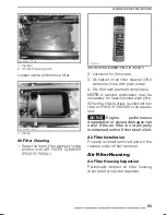
Page 97: ...n water 4 Dry the foam element completely NOTE A second application may be necessary for heavily soiled elements When the filter is dried re oiled with air filter oil P N 219 700 340 or an equiva lent NOTICE Engine performance degradation or severe damages can occur if the air filter is not properly maintained and or if it not well oiled Air Filter Installation Properly reinstall removed parts in ...

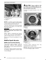
Page 98: ...filter as explained in this section Muffler Spark Arrester Muffler Spark Arrester Cleaning The muffler spark arrester must be periodically cleaned from accumu lated carbon Refer to MAINTENANCE SCHEDULE The entire exhaust system should also be visually inspected for cracks leaks or any damage CAUTION Never perform this operation immediately after the en gine has been running because ex haust system...

Page 99: ...is hot Let the radiator cool down before clean ing NOTICE Be careful not to damage the radiator fins when cleaning Do not use any object tool that could damage the fins The fins are pur posely thin parts to allow efficient cooling WHEN HOSING USE LOW PRESSURE ONLY DO NOT USE A HIGH PRESSURE WASHER Radiator Inspection Inspect radiator and hoses for leaks or any damage See an authorized Can Am deale...

Page 100: ... Below Specification If free play is less than specification refer to ADJUSTMENT AT CLUTCH COVER further Free Play Is Above Specification If free play is less than specification refer to ADJUSTMENT AT CLUTCH LEVER below Adjustment at Clutch Lever Turn cable adjuster until proper dimen sion is obtained vmo2010 012 004_a 1 Cable adjuster vmo2010 012 005_a CLUTCH LEVER PROPER ADJUSTMENT A 10 mm to 15...

Page 101: ...hrough clutch cover upper win dow if clutch cable and clutch release cam are fully released vmo2010 012 002_a 1 Clutch cable 2 Clutch release cam A 4 mm to 5 mm 16 in to 2 in Install CLUTCH ADJUSTMENT WRENCH 11 MM P N 529 036 076 provided in tool kit onto lock nut 529036076 CLUTCH ADJUSTMENT WRENCH vmo2008 011 071_a 1 Lock nut Hold adjustment screw using a flat screwdriver then loosen lock nut cou...

Page 102: ...utch adjustment wrench vmo2008 011 085_b 1 Screwdriver 2 Clutch adjustment wrench To confirm proper adjustment gen tly push on adjustment screw using a screwdriver A small axial play of ap proximately 0 5 mm 02 in should be felt If not perform adjustment again vmo2010 012 003_a 1 Adjustment screw A 0 5 mm 02 in NOTICE A premature clutch disk wear may occur if adjustment is too tight Reinstall acce...

Page 103: ...bricant like water based lubricant could cause the throttle lever cable to become sticky or stiff Remove the throttle lever housing cover vmo2008 011 001_d 1 Remove screws Remove cable from throttle lever vmo2008 011 108_a Remove the throttle body side cover vmo2008 011 101_a LH SIDE OF ENGINE 1 Remove screw 2 Cover 3 Throttle body Install the CABLE LUBER P N 529 035 738 or an equivalent on the ca...

Page 104: ...cant until it passes through the cable vmo2008 011 102_a 1 Look for lubricant here Reinstall the cable Spray a little quantity of lubricant on the throttle lever mechanism then close the housing Adjust the throttle lever Throttle Lever Throttle Lever Adjustment Slide rubber protector back to expose throttle cable adjuster vmo2008 011 072_a 1 Rubber protector Loosen lock nut then turn the adjuster ...

Page 105: ...rk plug cables vmo2008 011 082_a CABLES LOCATION Clean spark plugs and cylinder head with pressurized air if possible WARNING Always wear safety goggles when using pressurized air Unscrew and remove spark plugs vmo2008 011 083_a 1 Spark plugs Spark Plugs Installation Prior to installation make sure that contact surfaces of cylinder head and spark plugs are free of grime Using a feeler gauge set sp...

Page 106: ...K cable first Remove bolts retaining battery holder and rack vmo2008 011 044_a TYPICAL 1 RED 2 BLACK 3 Battery holder Remove battery Battery Cleaning Clean battery post and cable ends with a wire brush Battery Installation Reinstall battery in vehicle Fasten bat tery holder WARNING Connect RED cable first then BLACK cable Always connect RED cable first Apply DIELECTRIC GREASE P N 293 550 004 or an...

Page 107: ...SIDE 1 Fuse box Fuse and Relay Identification vmo2012 016 002_b FUSES 1 F1 Main 20A 2 F2 Cooling fan 10A 3 F3 Accessories 10A vmo2012 016 002_a RELAYS 1 R1 Main 2 R2 Fuel system 3 R3 Cooling fan Lights Beam Aiming Adjustment To adjust beam proceed as follows 1 Loosen the bolts shown on the fol lowing illustrations but do not re move them ______________ 105 ...

Page 108: ...leave a film on the bulb NOTE Concerning the following il lustrations the headlight housing has been removed from the vehicle for a better comprehension To replace the headlight bulb proceed as follows Turn the ignition switch to OFF posi tion Remove rubber protector from head light housing vmo2008 018 038_a TYPICAL 1 Rubber protector Unplug connector from headlight Push the retaining clip round e...

Page 109: ...ng counterclockwise to release Install the new bulb by pushing it in while turning clockwise Indicator Lamps Indicator Lamps Bulbs replacement Remove fuel tank cap Remove console vmo2008 011 050_a 1 Console Unplug wires on defective indicator lamp Press both taps then pull indicator lamp out of hole V02A0FY 1 1 1 Tabs For installation reverse the removal procedure Drive Chain WARNING Always turn i...

Page 110: ...hain lubricant Other commercial chain lubricants may contain solvent which could damage the O rings Drive Chain Adjustment Adjust the drive chain before every ride NOTE Always adjust drive chain with the driver or equivalent weight seated on the vehicle 1 Select a level surface and set trans mission to NEUTRAL Loosen rear axle lock bolts vmo2008 011 052_a 1 Rear axle lock bolts 2 Insert screw driv...

Page 111: ... Am dealer for replacement Drive Chain Sprockets Drive Chain Sprockets Inspection Check the sprockets for distortion V02H02Y 1 2 1 Good 2 Replace NOTICE Replace chain and sprockets together to prevent rapid chain and sprocket wear Install a new retaining ring each time the en gine sprocket is removed Tires Wheels Tire Pressure WARNING Tire pressure greatly affects vehi cle handling and stability I...

Page 112: ...s combined application may create handling and or stability problems Do not mix tires of different size and or design on the same axle Front tire pairs or rear tire pairs must be the identical model and manufacturer For unidirectional tread pattern ensure that the tires are installed in the correct direction of rotation The radial tires must be installed as a complete set Wheel Removal Loosen nuts...

Page 113: ...e Removal Beadlock Wheels 1 Remove wheel from the vehicle 2 Completely deflate tire 3 Loosen all beadlock bolts a few turns at a time in a criss cross pat tern 4 Remove beadlock bolts 5 Remove beadlock clamp ring vmo2012 016 004_b 1 Beadlock bolts 2 Beadlock clamp ring 6 Remove tire from the beadlock side Tire Installation Beadlock Wheels 1 Apply the tire mounting lube on the inner tire bead NOTIC...

Page 114: ... lbf in 9 lbf in vmo2012 016 003_a FIRST AND SECOND STEPS TIGHTENING SEQUENCE STEP FRONT WHEELS BEADLOCK TIGHTENING TORQUE Final step 8 N m 1 N m 71 lbf in 9 lbf in STEP REAR WHEELS BEADLOCK TIGHTENING TORQUE Final step 10 5 N m 1 N m 93 lbf in 9 lbf in vmo2012 016 003_b FINAL STEP TIGHTENING SEQUENCE The gap between tire and beadlock clamp ring should be equal all around the wheel vmo2012 016 004...

Page 115: ...ension Inspection Shock Absorbers Inspect shock absorber for oil leaks and fasteners for tightness See an autho rized Can Am dealer if necessary WARNING Shock absorbers are pressur ized An explosion may occur if heated or punctured Do not disassemble Suspension Arms Swing Arm and Linkage Inspection Check these parts for damages cracks dents excessive play or cor rosion pin holes If one of these da...

Page 116: ...05 008_a PIVOT ARM 1 Grease fitting Brakes Brake Fluid Level NOTE A low level may indicate leaks or worn brake pads See an authorized Can Am dealer Front Brake Fluid Reservoir Turn steering in the straight ahead po sition to ensure reservoir is level vmo2008 011 010_a TYPICAL 1 Front brake fluid reservoir Check brake fluid level through reser voir cover sight window A DARK color indicates a proper...

Page 117: ...rake fluid in reservoir for proper level vmo2008 011 013_a LOCATED NEAR THE RIGHT REAR FENDER 1 Rear brake fluid reservoir It should be above MIN mark vmo2008 011 018_a RH SIDE OF VEHICLE 1 Maximum level MAX 2 Minimum level MIN Clean and remove the filler cap then add fluid as required Do not overfill WARNING When installing the rear brake fluid reservoir filler cap make sure to return the rubber ...

Page 118: ...e disc protector for dam age replace if necessary SERVICE LIMITS Brake pads thickness 1 mm 04 in Discs thickness 3 5 mm 138 in Maximum discs warpage 0 2 mm 008 in See your authorized Can Am dealer if a problem is detected concerning the brake system WARNING The brake fluid replacement or brake system maintenance and repairs should be performed by an authorized Can Am dealer Body Seat Latch Remove ...

Page 119: ...reserve vehicle and its components and to keep lights clean Vehicle Cleaning and Protection Never use a high pressure washer to clean the vehicle USE LOW PRES SURE ONLY like a garden hose High pressure can cause electrical or mechanical damages Wrap up muf fler tip to avoid water infiltration in the exhaust system Painted parts which are damaged should be properly repainted to pre vent rust When r...

Page 120: ... specified in MAINTENANCE SCHEDULE When a vehicle is not in use for more than four months proper storage is a necessity See an authorized Can Am dealer for proper procedures When using your vehicle after stor age a preparation is required See an authorized Can Am dealer for proper procedures 118 ______________ ...

Page 121: ...TECHNICAL INFORMATION ______________ 119 ...

Page 122: ...vehicle identification number V I N is removed or mutilated in any way We strongly recommend that you take note of all the serial numbers on your vehicle and supply them to your insur ance company Vehicle Identification Number MFD DATEFAB 12 2003 2BPS1234X2V000123 1234 MODEL VIN NIV MANUFACTURED BY FABRIQUÉ PAR MADE IN FABRIQUÉ AU XXXXX TYPE ATV VTT 2 1 vmo2008 011 094_a TYPICAL VEHICLE SERIAL NUM...

Page 123: ...he vehicle after such device or element of design has been removed or rendered inoper ative by any person Among those Acts Presumed to Constitute Tampering are the Acts Listed Below 1 Removal or alteration or the punc turing of the muffler or any engine component which conducts re moval of engine exhaust gases 2 Removal or alteration or the punc turing of any part of the intake sys tem 3 Replacing...

Page 124: ...neously Lubrication Oil filter Synthetic multi layer oil filter Decompressor Automatic Exhaust system BRP stainless steel Air filter 2 stage foam filter TRANSMISSION Clutch Wet clutch multi disc Transmission Integrated 5 speeds constant mesh transmission COOLING Type Liquid cooled with integrated water pump Radiator Front mounted with thermostatic fan FUEL SYSTEM Type Electronic fuel injection wit...

Page 125: ...N 420 897 186 on spark plug threads Type DCPR9E Spark plug Gap 0 7 mm to 0 8 mm 028 in to 031 in Number of spark plug 2 Type Maintenance free battery type Battery Volt 12 volts 7 A h Starting system Electric start Start in any gear with clutch applied or on NEUTRAL Headlight bulb 2 x 35 W Taillight and brake light bulb 8 27 W 1157 F1 Main 20 A F2 Cooling fan 10 A Fuses F3 Accessories 10 A DRIVE TR...

Page 126: ...adjustable DS 450 DS 450 X xc 267 mm 10 5 in 267 mm 10 5 in Rear Travel DS 450 X mx 282 mm 11 1 in TIRES DS 450 DS 450 X xc 48 3 kPa 7 PSI maximum 34 5 kPa 5 PSI minimum Front DS 450 X mx 68 9 kPa 10 PSI maximum 55 2 kPa 8 PSI minimum DS 450 DS 450 X xc 48 kPa 7 PSI maximum 34 5 kPa 5 PSI minimum Pressure up to 100 kg 220 lb Rear DS 450 X mx 62 1 kPa 9 PSI maximum 48 3 kPa 7 PSI minimum DS 450 DS ...

Page 127: ...brake lever includes a parking brake on front wheels STEERING Toe in vehicle on ground and measure on the center of tire tread 0 mm to 6 35 mm 0 in to 25 in Caster adjustable on X xc and X mx Factory setting 8 Camber adjustable on X mx Factory setting 12 LOADING CAPACITY Total vehicle load allowed 100 kg 220 lb includes operator all other loads and added accessories DS 450 281 kg 620 lb DS 450 X x...

Page 128: ...t DS 450 X mx 1 10 m 43 3 in Wheelbase 1 27 m 50 in DS 450 1 m 39 5 in DS 450 X xc 1 04 m 40 9 in Front DS 450 X mx 1 08 m 42 5 in DS 450 909 mm 35 8 in DS 450 X xc 932 mm 36 7 in Wheel track measured at center of tread Rear DS 450 X mx 997 mm 39 3 in DS 450 229 mm 9 in DS 450 X xc 190 mm 7 5 in Under frame DS 450 X mx 180 mm 7 in DS 450 124 mm 4 9 in DS 450 X xc 103 mm 4 1 in Ground clearance Rea...

Page 129: ...oolant or a coolant specially designed for aluminum engines Type Premium unleaded gasoline Fuel Octane Inside North America 91 RON MON 2 Outside North America 95 RON Hydraulic brake Brake fluid DOT 4 CAPACITIES Fuel tank 11 5 L 3 U S gal including an approximate reserve of 2 5 L 7 U S gal Engine oil 1 8 L 1 9 qt U S liq Coolant 1 8 L 1 9 qt U S liq While reading this Operator s Guide remember that...

Page 130: ...SPECIFICATIONS This page is intentionally blank 128 ______________ ...

Page 131: ...TROUBLESHOOTING ______________ 129 ...

Page 132: ...e cranking Proceed as follows Insert key in ignition switch and turn to ON position Press completely and HOLD throttle lever Press the engine START button The engine should be cranked for 20 seconds Release engine START but ton Release throttle lever and start crank engine again to allow starting If it does not work Clean the spark plug caps area then remove them Remove the spark plugs refer to MA...

Page 133: ... TO START 2 Lack of fuel to engine Refer to ENGINE TURNS OVER BUT FAILS TO START 3 Engine is overheating check engine indicator lamp comes ON or flashes Refer to ENGINE OVERHEATS 4 Air filter housing clogged or dirty Check air filter and clean if necessary Check liquid deposits in air filter housing drain tube 5 Ignition coil disconnected Check ignition coils connection ENGINE OVERHEATS 1 Low cool...

Page 134: ...Contact an authorized Can Am dealer VEHICLE CANNOT REACH FULL SPEED 1 Engine Refer to ENGINE LACKS ACCELERATION OR POWER 2 Parking brake Ensure parking brake is completely removed 3 Air filter housing clogged or dirty Check air filter and clean if necessary Check liquid deposits in air filter housing drain tube TRANSMISSION DOES NOT SHIFT SMOOTHLY 1 Engine oil level is low Refill oil tank with rec...

Page 135: ...erheating Refer to ENGINE OVERHEATS 2 Low or high battery voltage Check battery voltage and charging system Contact an authorized Can Am dealer CHECK ENGINE INDICATOR LAMP FLASHES 1 Engine is under a protection mode limp home Contact an authorized Can Am dealer ______________ 133 ...

Page 136: ...TROUBLESHOOTING GUIDELINES 134 ______________ ...

Page 137: ...WARRANTY ______________ 135 ...

Page 138: ...ATION TO THE LIFE OF THE EXPRESS WARRANTY INCIDENTAL AND CONSE QUENTIAL DAMAGES ARE EXCLUDED FROM COVERAGE UNDER THIS WARRANTY SOME STATES PROVINCES DO NOT ALLOW FOR THE DIS CLAIMERS LIMITATIONS AND EXCLUSIONS IDENTIFIED ABOVE AS A RESULT THEY MAY NOT APPLY TO YOU THIS WARRANTY GIVES YOU SPECIFIC RIGHTS AND YOU MAY ALSO HAVE OTHER LEGAL RIGHTS WHICH MAY VARY FROM STATE TO STATE OR PROVINCE TO PROV...

Page 139: ...thirty 30 consecutive months whichever comes first and evaporative emission related components are warranted for twenty four 24 consecutive months To obtain a list of the current warranted emission related components please see an authorized Can Am ATV dealer The repair or replacement of parts or the performance of service under this war ranty does not extend the life of this warranty beyond its o...

Page 140: ...e the property of BRP 7 WHAT BRP WILL DO BRP s obligations under this warranty are limited to at its sole discretion repairing parts found defective under normal use maintenance and service or replacing such parts with new genuine Can Am ATV parts without charge for parts and labor at any authorized BRP dealer during the warranty coverage period under the conditions described herein No claim of br...

Page 141: ...y equipped with Carlisle or ITP branded ATV tires The tires are warranted separately by the tire manufacturer and are not covered by this limited warranty Please contact the manufacturer or ask your au thorized Can Am ATV dealer for assistance Carlisle Tire Wheel Company 23 Windham Boulevard Aiken SC 29805 Warranty Information USA 1 800 260 7959 Canada 1 800 265 6155 Quebec 1 877 997 4999 9 TRANSF...

Page 142: ...number below In Canada BOMBARDIER RECREATIONAL PRODUCTS INC CAN AM ATV CUSTOMER ASSISTANCE CENTER 75 J A Bombardier Street Sherbrooke QC J1L 1W3 Tel 819 566 3366 In USA BRP US INC CAN AM ATV CUSTOMER ASSISTANCE CENTER 7575 Bombardier Court Wausau WI 54401 Tel 715 848 4957 In the USA products are distributed and serviced by BRP US Inc 2010 Bombardier Recreational Products Inc All rights reserved TM...

Page 143: ...fied to change its intended use 2 LIMITATIONS OF LIABILITY THIS WARRANTY IS EXPRESSLY GIVEN AND ACCEPTED IN LIEU OF ANY AND ALL OTHER WARRANTIES EXPRESSED OR IMPLIED INCLUDING WITHOUT LIMITATION ANY WARRANTY OF MERCHANTABILITY OR FITNESS FOR A PARTICULAR PURPOSE TO THE EXTENT THAT THEY CANNOT BE DISCLAIMED THE IMPLIED WARRANTIES ARE LIMITED IN DURATION TO THE LIFE OF THE EXPRESS WARRANTIES INCIDEN...

Page 144: ... WARRANTY COVERAGE PERIOD This warranty will be in effect from 1 the date of delivery to the first retail con sumer or 2 the date the product is first put into use whichever occurs first and for a period of SIX 6 CONSECUTIVE MONTHS for private use or commercial use The repair or replacement of parts or the performance of service under this war ranty does not extend the life of this warranty beyond...

Page 145: ...WILL DO BRP s obligations under this warranty are limited to at its sole discretion repairing parts found defective under normal use maintenance and service or replacing such parts with new genuine Can Am ATV parts without charge for parts and labour at any authorized Can Am ATV Distributor Dealer during the warranty coverage period under the conditions described herein BRP s responsibility is lim...

Page 146: ...er Assistance Center Skaldenstraat 125 9042 Gent Belgium Tel 32 9 218 26 00 For Scandinavian countries please contact our Finland office BRP FINLAND OY Service Department Isoaavantie 7 FIN 96320 Rovaniemi Finland Tel 358 16 3208 111 For all other countries please contact your local Can Am ATV Distributor Dealer visit our website at www brp com for contact information or contact our North America o...

Page 147: ...ered or modified to change its intended use 2 LIMITATIONS OF LIABILITY THIS WARRANTY IS EXPRESSLY GIVEN AND ACCEPTED IN LIEU OF ANY AND ALL OTHER WARRANTIES EXPRESSED OR IMPLIED INCLUDING WITHOUT LIMITATION ANY WARRANTY OF MERCHANTABILITY OR FITNESS FOR A PARTICULAR PURPOSE TO THE EXTENT THAT THEY CANNOT BE DISCLAIMED THE IMPLIED WARRANTIES ARE LIMITED IN DURATION TO THE LIFE OF THE EXPRESS WARRAN...

Page 148: ...D This warranty will be in effect from 1 the date of delivery to the first retail con sumer or 2 the date the product is first put into use whichever occurs first and for a period of TWENTY FOUR 24 CONSECUTIVE MONTHS for private use SIX 6 CONSECUTIVE MONTHS for commercial use or rental use The product is used commercially when it is used in connection with any work or employment that generates inc...

Page 149: ...ir in order to validate the warranty repair All parts replaced under this limited warranty become the property of BRP Note that the notification period is subject to the applicable national or local legisla tion in your country 7 WHAT BRP WILL DO BRP s obligations under this warranty are limited to at its sole discretion repairing parts found defective under normal use maintenance and service or r...

Page 150: ...d discussing the issue with the Can Am ATV Distributor Dealer s service manager or owner You will find your Can Am ATV Distributor Dealer s coordinates on our website at www brp com 2 If further assistance is required the Can Am ATV Distributor s service depart ment should be contacted in order to resolve the matter 3 If the matter still remains unresolved then contact BRP at the address listed be...

Page 151: ...PRODUCTS INC Customer Assistance Center 75 J A Bombardier Street Sherbrooke QC J1L 1W3 Tel 819 566 3366 For the territory covered by this limited warranty products are distributed and serviced by Bombardier Recreational Products Inc or its affiliates 2010 Bombardier Recreational Products Inc All rights reserved TM Trademark of Bombardier Recreational Products Inc or its affiliates ______________ 1...

Page 152: ...mple or model Have the qualities that a buyer may legitimately expect considering the pub lic declarations of the seller the manufacturer of its representative including in advertising or labeling or 2 Have the characteristics mutually agreed upon as between the parties or be fit for the specific use intended by the buyer and brought to the attention of the seller and which accepted The action for...

Page 153: ...CUSTOMER INFORMATION ______________ 151 ...

Page 154: ...stomer list to distribute marketing and promotional information about BRP and related products To exercise your right to consult or correct your data or to be removed from the ad dressee list for direct marketing please contact BRP By E mail privacyofficer brp com By mail BRP Senior Legal Counsel Privacy Officer 726 St Joseph Valcourt QC Canada J0E 2L0 152 ______________ ...

Page 155: ...wner if necessary like when safety recalls are initiated It is the owner s responsibility to notify BRP STOLEN UNITS If your personal ATV is stolen you should notify BRP or an autho rized Can Am dealer We will ask you to provide your name address phone num ber the vehicle identification number and the date it was stolen In North America BOMBARDIER RECREATIONAL PRODUCTS INC Warranty Department 75 J...

Page 156: ...CHANGE OF ADDRESS OWNERSHIP This page is intentionally blank 154 ______________ ...

Page 157: ...CHANGE OF ADDRESS OWNERSHIP ______________ 155 ...

Page 158: ...CHANGE OF ADDRESS OWNERSHIP 156 ______________ ...

Page 159: ... completed by the dealer at the time of the sale DEALER IMPRINT AREA NAME No STREET APT CITY STATE PROVINCE ZIP POSTAL CODE V00A2IL Please verify with your dealer to ensure your vehicle has been registered with BRP While reading this Operator s Guide remember that WARNING Indicates a potential hazard that if not avoided could result in serious injury or death ...

Page 160: ...you operate this vehicle on pavement NEVER OPERATE THIS VEHICLE ON PUBLIC ROADS You can collide with another vehicle if you operate this vehicle on a public road ALWAYS WEAR AN APPROVED HELMET eye protection and protective clothing NEVER RIDE UNDER THE INFLUENCE OF ALCOHOL OR DRUGS They slow reaction time and impair judgment NEVER OPERATE THIS VEHICLE AT EXCESSIVE SPEEDS You increase your risk of ...

Reviews: