background image

www.canadiansolar.com

| 7

·  Only modules with similar electrical outputs  

should be connected in the same series to avoid  
or minimize mismatch effects in arrays.

·  To minimize risk in the event of an indirect light-

ning strike, avoid forming loops when designing 
the system.

·  The recommended maximum series fuse rating  

is stated in a table in the Annex.

·  Modules should be safely fixed to bear all expected 

loads, including wind and snow loads. 

·   A minimum clearance of 10 mm (0.394 in) or more 

between modules is required to allow for thermal 
expansion of the modules. The clearance is from 
the plastic corner protector to adjacent plastic 
corner protector.

OPTIMUM ORIENTATION AND TILT

·  To maximize your annual yield, find out the optimum 

orientation and tilt for PV modules in your region. 
The highest yields are achieved when sunlight 
shines perpendicularly onto the PV modules.

AVOID SHADING

·  Even minor partial shading (e.g. from dirt deposits) 

reduces yields. A module can be considered to be 
unshaded if its entire surface is free from shading 
all year round. Sunlight should be able to reach the 
module even on the shortest day of the year.

·  Permanent shading conditions can affect module 

service lifetime, due to accelerated ageing of the 
encapsulation material and thermal stress on the 
bypass diodes.

RELIABLE VENTILATION

·  Sufficient clearance (at least 10 cm (3.94 in)) bet

-

ween the module frame and the mounting surface 
is required to allow cooling air to circulate 

   around the back of the module. This also enables 

condensation or moisture to dissipate. 

·  According to UL 1703, any other specific clearan

-

ce required for maintaining a system fire rating 

should prevail. Detailed clearance requirements 

pertaining to system fire ratings must be provided 

by your racking supplier.

5.1  

MODULE WIRING

CORRECT WIRING SCHEME


·  Ensure that the wiring is correct before starting up 

the system. If the measured open circuit voltage 
(Voc) and short-circuit current (Isc) differ from the 

specifications, this indicates that there is a wiring 

fault.  

 
·  When modules have been pre-installed but the 

system has not been connected to the grid yet, 
each module string should be kept under open-cir-
cuit conditions and proper actions should be taken 
to avoid dust and moisture penetration inside the 
connectors.

·  For CS3U and CS3K series modules, Canadian Solar 

Inc. offers optional cable specifications to match 
various system configurations. Recommended 

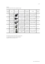
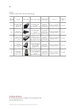
system cable schemes are shown in table 1:

Summary of Contents for CS3K-MS-FG

Page 1: ...INSTALLATION MANUAL OF DYMOND MODULE For professional use only ...

Page 2: ...NICAL ELECTRICAL SPECIFICATIONS 4 0 UNPACKING AND STORAGE 5 0 MODULE INSTALLATION 5 1 MODULE WIRING 5 2 MODULE GROUNDING 6 0 MOUNTING INSTRUCTIONS 7 0 MAINTENANCE AMENDED EDITIONS AND DATES ANNEX A MECHANICAL AND ELECTRICAL RATINGS ANNEX B DOUBLE GLASS MODULE INSTALLATION MANUEL SUPPLEMENT 3 3 3 3 4 8 5 9 5 10 7 10 11 14 2 1 INFORMATION PURSUANT TO ART 33 OF THE REACH REGULATION 3 ...

Page 3: ...all not be held responsible for damages of any kind including without limitation bodily harm injury or damage to property in connection with handling PV modules system installation or compliance or non compliance with the instructions set forth in this manual 2 0 SAFETY PRECAUTIONS Warning Before attempting to install wire operate and or service the module and other electrical equipment all inst r...

Page 4: ...bstance of Very High Concern SVHC in a concentration above 0 1 weight by weight The coating of the ribbon of our solar modules contains lead CAS no 7439 92 1 Under normal or reasonably foreseeable conditions of use exposure to the lead that is contained in our solar modules can be excluded However a release of and expo sure to lead can take place i when the different components of the solar module...

Page 5: ...les under any circumstances Localized heavy loads may cause severe micro cracks at cell level which in turn may compromise module reliability and void Canadian Solar Inc s warranty Do not drop or place objects such as tools on the modules Do not carry modules on your head Do not use sharp instruments on the modules Do not place modules on top of each other Do not leave modules unsupported or unsec...

Page 6: ...ing system supplier ENVIRONMENTAL CONDITIONS The module is intended for use in general open air climates as defined in IEC 60721 2 1 Classification of environmental conditions Part 2 1 Environmental conditions appearing in nature temperature and humidity Please consult the Canadian Solar Inc technical support department for more information on the use of modules in special climates Do not install ...

Page 7: ...ear Permanent shading conditions can affect module service lifetime due to accelerated ageing of the encapsulation material and thermal stress on the bypass diodes RELIABLE VENTILATION Sufficient clearance at least 10 cm 3 94 in bet ween the module frame and the mounting surface is required to allow cooling air to circulate around the back of the module This also enables condensation or moisture t...

Page 8: ...in North America and single conductor cable 2 5 16 mm 5 14 AWG 90 C wet rated in other areas i e TUV 2PfG1169 or EN50618 approved with proper insulation which is able to withstand the maximum possible system open cir cuit voltage Only copper conductor material should be used Select a suitable conductor gauge to minimize vol tage drop and ensure that the conductor ampacity complies with local regul...

Page 9: ...ing torques should respectively be within 17 23 Nm 12 5 17 0 ft lb for M8x1 25 Grade 8 8 5 16 18 Grade B7 galvanized or A2 70 stainless steel coarse thread bolts depending on bolt class The yield strength of bolt and nut should not be less than 450 MPa Use appropriate corrosion proof fastening materi als All mounting hardware bolts spring washers flat washers nuts should be hot dip galvanized or s...

Page 10: ... not make modifications to any component of the PV module diode junction box plug connectors or others Regular maintenance is required to keep modules clear of snow bird droppings seeds pollen leaves branches dirt spots and dust Modules with sufficient tilt at least 15 generally do not require cleaning rain will have a self cleaning effect If the module has become soiled it shall be washed with wa...

Page 11: ...FG 395 40 6 9 73 48 4 10 25 CS3U 400MS FG 400 40 8 9 81 48 6 10 33 CS3U 405MS FG 405 41 9 88 48 8 10 41 CS3U 410MS FG 410 41 2 9 96 49 10 49 CS3U 310P FG 310 37 2 8 34 44 7 8 88 30 2000 x 992 x 5 8 78 7 x 39 1 x 0 23 in Without junction box and corner protector 29 63 9 lbs CS3U 315P FG 315 37 4 8 43 44 9 8 96 CS3U 320P FG 320 37 6 8 52 45 1 9 04 CS3U 325P FG 325 37 8 8 6 45 3 9 12 CS3U 330P FG 330...

Page 12: ...56 40 1 9 97 CS3K 325P FG 325 33 7 9 65 40 3 10 05 CS6K 245P FG 245 30 0 8 17 37 1 8 74 15 1658 ˣ 992 ˣ 5 8 65 3 ˣ 39 1 ˣ 0 23 in without junction box and corner protector 23 50 7 lbs CS6K 250P FG 250 30 1 8 30 37 2 8 87 CS6K 255P FG 255 30 2 8 43 37 4 9 00 CS6K 260P FG 260 30 4 8 56 37 5 9 12 CS6K 265P FG 265 30 6 8 66 37 7 9 23 CS6K 270P FG 270 30 8 8 75 37 9 9 32 CS6K 275P FG 275 31 0 8 88 38 0...

Page 13: ...mm 77 5ˣ 39 1 ˣ 0 23 in without junction box and corner protector 27 5 60 6 lbs CS6X 295P FG 295 36 0 8 19 44 5 8 76 CS6X 300P FG 300 36 1 8 30 44 6 8 87 CS6X 305P FG 305 36 3 8 41 44 8 8 97 CS6X 310P FG 310 36 4 8 52 44 9 9 08 CS6X 315P FG 315 36 6 8 61 45 1 9 18 CS6X 320P FG 320 36 8 8 69 45 3 9 26 CS6X 325P FG 325 37 0 8 78 45 5 9 34 CS6X 330P FG 330 37 2 8 88 45 6 9 45 CS6X 335P FG 335 37 4 8 ...

Page 14: ...on and local climate Determination of the design loads is the responsibility of the racking suppliers and or professional engineers For detailed information please follow local structural code or contact your professional structural engineer Corner protector is not included in below illustrations A A A A Clamping on module long side four clamp points Mounting rails must run perpendicularly to the ...

Page 15: ...amp length 100 mm four clamps A 380 20 mm see illustration A Downforce load 2400 Pa Uplift load 2400 Pa VDE CSA 2 C 2 Profi clamp wide 3 8 mm clamp length 200 mm four clamps A 380 20 mm see illustration A Downforce load 5400 Pa Uplift load 2400 Pa VDE CSA 2 C 3 Profi clamp wide 3 8 mm clamp length 80 mm six clamps A 250 20 mm B 579 20 mm see illustration B Downforce load 2400 Pa Uplift load 2400 P...

Page 16: ...ength 100 mm six clamps A 250 20 mm B 579 20 smm see illustration B Downforce load 5400 Pa Uplift load 2400 Pa VDE CSA 2 F 1 Akcome Metals Technology Suzhou Co Ltd AK EC DG End clamp AK MC DG Middle clamp clamp length 100 mm four clamps A 380 20 mm see illustration A Downforce load 2400 Pa Uplift load 2400 Pa VDE CSA 2 F 2 AK EC DG End clamp AK MC DG Middle clamp clamp length 200 mm four clamps A ...

Page 17: ...fi clamp wide 3 8 mm clamp length 130 mm four clamps A 440 20 mm see illustration A Downforce load 2400 Pa Uplift load 2400 Pa VDE CSA 3 C 2 Profi clamp wide 3 8 mm clamp length 250 mm four clamps A 440 20 mm see illustration A Downforce load 5400 Pa Uplift load 2400 Pa VDE CSA 3 C 3 Profi clamp wide 3 8 mm clamp length 100 mm six clamps A 300 20mm B 684 20 mm see illustration B Downforce load 240...

Page 18: ... mm B 684 20 mm see illustration B Downforce load 5400 Pa Uplift load 2400 Pa VDE CSA 3 F 1 Akcome Metals Technology Suzhou Co Ltd AK EC DG End clamp AK MC DG Middle clamp clamp length 130 mm four clamps A 440 20 mm see illustration A Downforce load 2400 Pa Uplift load 2400 Pa VDE CSA 3 F 2 AK EC DG End clamp AK MC DG Middle clamp clamp length 250 mm four clamps A 440 20 mm see illustration A Down...

Page 19: ...2400 Pa VDE CSA 4 C 1 Xiamen Grace SolarTechnology co ltd GS IC Middle clamp GS EC End clamp clamp length 200 mm four clamps A 380 20 mm see illustration A Downforce load 5400 Pa Uplift load 2400 Pa VDE CSA 4 D 1 Powerway Renewable Energy Co Ltd PW CS 01 End clamp PW CS 02 Middle clamp clamp length 200 mm four clamps A 380 20 mm see illustration A Downforce load 5400 Pa Uplift load 2400 Pa VDE CSA...

Page 20: ...etter GmbH Profi clamp wide 3 8 mm clamp length 250 mm four clamps A 440 20 mm see illustration A Downforce load 5400 Pa Uplift load 2400 Pa VDE CSA 5 C 1 Xiamen Grace SolarTechnology co ltd GS IC Middle clamp GS EC End clamp clamp length 250 mm four clamps A 440 20 mm see illustration A Downforce load 5400 Pa Uplift load 2400 Pa VDE CSA 5 D 1 Powerway Renewable Energy Co Ltd PW CS 01 End clamp PW...

Reviews: