background image

Summary of Contents for CSI-25KTL-GS-FLB

Page 1: ...9 Sales Inquiries Email sales us canadiansolar com Technical Inquiries Email service ca canadiansolar com This manual is subject to change without prior notification Copyright is reserved Duplication of any part of this issue is prohibited without written permission CanadianSolar CSI SERIES GRID TIED PV Inverter CSI 25KTL GS FLB CSI 30KTL GS FLB CSI 36KTL GS FLB CSI 40KTL GS FLB INSTALLATION AND O...

Page 2: ...anadian Solar equipment has supplied The customer is fully liable for any modifications made to the system therefore any hardware or software modification manipulation or alteration not expressly approved by the manufacturer shall result in the immediate cancellation of the warranty Given the countless possible system configurations and installation environments it is essential to verify adherence...

Page 3: ...23 3 6 Making connections to theAC side of the inverter 24 3 6 1 Connecting the inverter to the utility grid 25 3 6 2 Wiring procedure 25 CanadianSolar Contents 3 7 Installing the inverter 26 3 8 External ground connection point 31 4 Communication Monitoring 32 4 1 RS485 33 4 1 1 Wiring a single inverter and daisy chain inverter 33 4 1 2 Maximum allowable inverters using RS485 33 4 1 3 120 ohm 0 r...

Page 4: ...aiEPMset 75 6 8 Arc fault current interrupt AFCI function 75 7 Maintenance 76 8 Troubleshooting 77 8 1 Current alarm front LCD panel 77 8 1 1 Running messages 77 8 2 Alarm history 77 8 2 1 Viewing alarm history 77 8 3 Error messages 77 8 3 1 Troubleshooting guide 77 9 Appendices 82 10 Specifications 90 CanadianSolar 1 Introduction 1 1 Product Description Canadian Solar Three Phase Inverters conver...

Page 5: ... Hexagon bolt M6 12 1 3 Handle M10 2 1 4 Installation instructions 1 Inverter power train packing list D H 6 2 1 no D EJ 2 5 2 2 B 0 2 3 2 4 CanadianSolar 1 Introduction Part Description Number 2 1 Inverter wire box 1 2 2 Wire box mounting plate 1 2 3 Power Train mounting plate 1 2 4 Wire box package accessories 1 2 4 1 Hexagon bolt M1 0 40 6 2 4 2 Flat Washer M1 0 6 2 4 3 Hexagon nut 6 2 4 4 Hexa...

Page 6: ...n and dust that has settled inside the equipment will be required 8 DO NOTSTACK MORE11 IAN 2 HIGH Figure 1 3 canadianSolar 2 Safety Instructions Improper use may result in electric shock hazards or burns This product manual contains important instructions that are required to be followed during installation and maintenance Please read these instructions carefully before use and keep them in an eas...

Page 7: ...inverter the Grid Supply Main Switch AC must be turned on BEFORE the DC Switch is turned on To stop the inverter the Grid Supply Main Switch AC must be turned off before the DC Switch is turned off 10 canadianSolar 2 Safety Instructions 2 4 Protection Circuitry and Controls To meet relevant codes and standards the Canadian Solar three phase inverter line is equipped with protective circuitry and c...

Page 8: ...cked Adequate ventilation must be present if the inverter is to be installed in a confined space I I 20in 20in I I Figure 3 1 Distances required between inverters NOTE Nothing should be stored on or placed against the inverter 12 CanadianSolar 3 Installation 3 1 1 1 Examples of correct and incorrect installations u I I b b I I FJ NEMA4X FJ I X I u u b I F t FJ FJ X GJ fgg X X NOTE Units with a fan...

Page 9: ...e red circles below denote cutouts on the product package Push in the cutouts to form handles for moving the inverter see Figure 3 2 Inverter carton Wire box carton Figure 3 2 Handles used to move the inverter shown circled in red 2 Two people are required to remove the inverter from the shipping box Use the handles integrated into the heat sink to remove the inverter from the carton see Figure 3 ...

Page 10: ...g rack must be equal to or stronger than the marked rack 40mm 60mm 2mm CanadianSolar 3 Installation NOTE Inverter must not be mounted on a post or pole Damage to inverter or mounting bracket may occur Inverter must be mounted on a frame as shown or on a wall or other flat surface X 1 Installation of mounting wire box bracket Use 4 sets hexagon head bolts M4 40 flat washer M10 nut M10 to attach the...

Page 11: ...re box with two M6 screws on both sides and tighten them the torque is 4 6 N m 18 CanadianSolar 3 Installation 5 Use two M6 screws and locking plates on each side Do not tighten as these will be used later 6 Unscrew the four M5 captive screws on the wire box cover and remove the cover 19 ...

Page 12: ......

Page 13: ......

Page 14: ...3 2 Over current protection device characteristics for Canadian Solar inverters CanadianSolar 3 Installation 3 6 1 Connecting the inverter to the utility grid All electrical installations must be carried out in accordance with the local standards and the National Electrical Code ANSI NFPA 70 or the Canadian Electrical Code CSA C22 1 TheAC and DC electric circuits are isolated from the enclosure If...

Page 15: ......

Page 16: ... each side the torque is 1 6 2 N m Tighten the M6 screws loosened in Step 2 the torque is 4 6N m Hex screw M6 Figure 3 18 NOTE 1 Before installation it is necessary to ensure the switches on both sides of the wire box are turned OFF The switch knob should point to the OFF 2 There are two ways to install the inverter A Hoisting recommended There are 2 hoisting holes on both sides of the inverter B ...

Page 17: ...provided on the right side of the inverter To use the OPTIONAL external ground connection see Figure 3 23 1 Prepare the grounding conductor Crimp a ring or fork M4 size terminal onto the grounding conductor 2 Connect the grounding conductor with crimped terminal to the external ground connection point on the right side of the inverter Use a maximum torque of 20 in lbs 2N m Figure 3 23 Connect the ...

Page 18: ...erminal 5 RJ45 connector to connect use the following wiring sequence Connect the Ethernet cable according to the TIA EIA 5688 standard Insert the wire into the RJ45 plug and then use a standard network cable crimping tool to crimp connector to the cable 4 1 RS485 4 1 1 Wiring a single inverter and daisy chain inverters Correspondence between the cables and the stitches of plug Pin 1 white and ora...

Page 19: ...mized according to the local standard before shipping There should be no requirement to set the standard NOTE The User Def function can only be used by the service engineer and changing the protection level must be allowed by the local utlilty 1 From the main screen on the display select ENTER There are 4 submenu options use the UP DOWN arrows to highlight ADVANCED SETTINGS Press enter to select M...

Page 20: ...verter damage or the inverter to not operate at all Only certified personnel should set the grid standard Only set the grid configuration that is approved by your location and national grid standards 1 Please refer to section 6 7 Advanced Settings for procedures to create a custom grid configuration for User Def menu option 5 4 Preliminary checks WARNING High Voltage AC and DC measurements should ...

Page 21: ...ture reverse polarity protection prolonged connection in reverse polarity may damage these protection circuits and or the inverter 5 4 3 2 Leakage to ground Measure leakage to ground CanadianSolar 5 Commissioning 5 4 3 2 1 Detection of leakage to ground Canadian Solar inverters are transformer less and do not have an array connection to ground Any measurement of a fixed voltage between ground and ...

Page 22: ......

Page 23: ......

Page 24: ... 6V 232 0V 231 0V 230 5V I_DC1 I_DC2 I_DC3 I_DC4 I_A 1_8 I_C 1 2 15 90A 15 70A 15 30A 16 10A 43 5A 43 7A 43 4A Figure 6 5 Information screen 1 CanadianSolar 6 Normal operation Information 2015 02 23 19 35 Status Generating Total Energy 0003687kWh Frequency This Year 0000014kWh DRM NO Last Year 0000001 kWh This Month 0508kWh Last Month 2081kWh Today 0071 6kWh Yesterday OOOO OkWh Inverter SN FEFFFEF...

Page 25: ...the address Press the ENTER key to save the settings Press the ESC key to cancel the change and return to the previous menu Set Address 2015 02 23 19 35 Slave Address m J YES ENT NO ESC Figure 6 9 Address setting 46 CanadianSolar 6 Normal operation 6 5 3 Current system version This function is used to view the current system version See Figure 6 1 0 Updater 2015 02 23 19 35 The Current HMI Version...

Page 26: ...5 0000 NO Grid 02 23 19 34 0000 NO Grid 02 23 19 34 0000 NO Grid 02 23 19 24 0000 NO Grid 02 23 18 22 0000 01 40 Figure 6 13 Alarm messages 48 CanadianSolar 6 Normal operation 6 6 2 Running Message The screen shows the inverter s internal operational parameters see Figure 6 14 6 6 3 Version Running Message 2015 02 23 19 35 DC Bus Voltage 113 9V DC Bus Half Voltage 150 7V Reactive Power Ratio 0 98 ...

Page 27: ...17 Press the ENTER key to move cursor or press the UP or DOWN key to select energy data for a different date Daily Energy 2015 02 23 19 35 Figure 6 17 Daily power generation capacity 50 CanadianSolar 6 Normal operation 6 6 6 Monthly Energy The screen shows the inverter s daily energy detail for the month see Figure 6 18 Press the ENTER key to move cursor and press the UP or DOWN key to select ener...

Page 28: ...r service technicians only The inverter is customized according to the local standard before shipping There should be no requirement to set the standard The User Def function can be only used by the service engineer and changing the protection level must be approved by the local grid company Select grid standard see Figure 6 22 Select Standard 2015 02 23 19 35 Select Standard 1 11iJI UI YES ENT NO...

Page 29: ...G F2 57 59Hz UN G V2 T 0 1 1S UN G F2 T 0 1 9S Table 6 1 Setting ranges for User Def 54 CanadianSolar 6 Normal operation Setting value 480V Rated L L 480V Rated L N Vup Limit1 528 V 576 305 V 333 Time1 1S 1S Vup Limit2 V 576 V 333 Time2 0 16S 0 16S Vdw Limit1 288 V 422 166 V 244 Time1 2S 2S Vdw Limit2 V 288 V 166 Time2 0 16S 0 16S Fup Limit1 60 5Hz F 62Hz 60 5Hz F 62Hz Time1 2S 2S Fup Limit2 F 62H...

Page 30: ... Figure 6 26 Power Control 2015 02 23 19 35 L Jl Reactive Power Control Output Power Cortrol With Restore Reactive Power Control With Restore Figure 6 26 Power setting NOTE This function should be accessed by qualified maintenance personnel only The inverter operating in the wrong power setting will prevent the inverter from reaching maximum power 6 7 4 Clear Energy and Restore Settings Clear Ener...

Page 31: ... Password X X X YES ENT NO ESC Figure 6 28 Password setting 58 CanadianSolar 6 Normal operation After entering the current password you can create a new password Upon confirming the new password press the ENTER key to execute the new setting see Figure 6 29 Reset Password 2015 02 23 19 35 Please Input New Password X X X YES ENT NO ESC Figure 6 29 Set new password 6 7 7 Restart HMI The function reb...

Page 32: ...on 6 7 8 1 5 GRID INTF 02 A This function is applicable by maintenance personnel only wrong operation will prevent the inverter from reaching maximum power 6 7 8 1 6 MPPT Parallel This is used for parallel strings into different inverters MPPTs Press Enter and press up or down to change the settings Selecting RUN will enable parallel strings setup All MPPT channels will operate in parallel Selecti...

Page 33: ... compensation leakage current limitation insulation resistance limitation etc There are 6 items in lgZero Set submenu 62 lgZero Set 2015 02 23 19 35 lgrid A Zero 00 lgrid B Zero 00 lgrid C Zero 00 VFB AdJ Scale 00 ILeak Limit Riso Limit OOOmA OOOOk SET ENT DONE ESC Figure 6 33 lgZero Set CanadianSolar 6 Normal operation 6 7 8 4 VgCompensation This function is used to calibrate inverter output volt...

Page 34: ...or maintenance personnel only wrong operation will prevent the inverter from reaching maximum power 3 Volt Var Default Description Inverter will change the reactive output power based on voltage change i I 02 03 0 r Q4 ind i n_o_ i _ v_ 4______ Q1 cap Figure 6 24 Volt VAR curve for Q V 64 CanadianSolar 6 Normal operation Default Settings for UL1741SA Q1 0 60 Default 30 Q4 60 0 Default 30 Rated 480...

Page 35: ...tt Setting for UL1741 SA Standards 100 of Input Power 0 Vmin Vnom Vstart Figure 6 28 Volt Watt characteristic Default Settings for UL1741 SA Rated 480V Grid V1 less than V2 V2 1ess than Vstart V3 Vstart 277 333V Default305V V4 Vstop 305 360V Default 333V P1 100 P2 100 P3 100 P4 0 66 ACVolt Vstop Vmax CanadianSolar 6 Normal operation VgWatt UL 2015 02 23 19 35 Voltage1 242V P Limit1 Voltage2 P Limi...

Page 36: ...rger than Vstop P1 100 P2 100 P3 0 P4 0 110 Voltage Volt Watt 2015 02 23 19 35 Voltage1 254V P Limit1 100 Voltage2 293V P Limit2 100 Voltage3 304V P Limit3 100 Voltage4 318V P Limit4 000 SET ENT DONE ESC Figure 6 34 Volt Watt 68 CanadianSolar 6 Normal operation 3 Volt Var Description Inverter will change the reactive output power based on voltage change Q1 cap I Q2 Q3 0 ri i i _ v_4__________ Q4 i...

Page 37: ...VgWatt UL Not Required Description Inverter will change the active output power based on voltage change Note This Setting is NOT required by Rule21 Standards This function is for maintenance personnel only wrong operation will prevent the inverter from reaching maximum power 8 Enable both Volt Var and Volt Watt modes Description Rule21 requires both Volt var and Volt watt modes can be enabled To s...

Page 38: ...ey may not conform to the UL 1741 SA standard 72 CanadianSolar 6 Normal operation 6 7 9 3 Freq Derate Set Mode 04 is used for UL 1741 SA frequency derating setting_ 100 of Available Power i rldF eq eooy o L f min f nom f start f stop f max Figure 6 39 Mode 04 Freq Watt characteristic Over frequency load shedding F start range 59 936 60 036Hz default setting 60 036Hz Descending rate 5 Pn 0 1 Hz F s...

Page 39: ... t change settings in this item External EPM set Fail Safe Switch YES ENT NO ESC Figure 6 41 External EPM set 6 8 Arc fault current interrupt AFCI function The Canadian Solar Three Phase inverter series can be supplied with an integrated AFCI module which can detect and interrupt a serial arc in the DC circuit s If an arc fault occurs the AFCI module will detect the arc and interrupt the circuit T...

Page 40: ...er to Section 6 1 lfthe failure persists please first contact your local distributor and then Canadian Solar Support Service If you need to contact Canadian solar Support Service at North South Central America Canadian Solar Inc Attn Customer Service Department 3000 Oak Road Suite 400 Walnut Creek CA 94597 Tel 1 855 315 8915 E mail service ca canadiansolar com Please have the following information...

Page 41: ... inverter Test DC Switch ON Test DC switch OFF CheckAC at the inverter Check grid standard Replace inverter IfAC measures high adjust upper limit with Test DC switch OFF permission from utility Check DC at the inverter test points OV G V Over Inverter detects grid Test DC Switch ON full power OV DC DC If DCV is high too many panels in the string Grid Voltage voltage as too high CheckAC at inverter...

Page 42: ...ion OV TEM Inverter detects high Check heatsink for obstructions ventilation Temperature ambient temperature 60C Is inverter in direct sunshine Protection Measure ambient temperature near inverter lftemp is in range replace inverter Inspect installation Reset inverter PV ISO PRO Note weather conditions when alarm occurs 01 02 Inverter detects low DC Measure insulation resistance Ground insulation ...

Page 43: ... continuous output power Watts 25000 Compliance IEEE 1547 FCC Part 15 Class A B Nominal grid voltage Volts 480 CAN CSAC22 2107 1 1 Rule21 Phaesl 11 111 Operating voltage range Volts 422 4 528 Operating surroundings humidity 0 100 Condensing Nominal grid frequency Hertz 60 Features Operating frequency range Hertz 59 5 60 5 Interface RS485 optional WiFi Operating phase 3 PE Display 7 0 LCD color scr...

Page 44: ... continuous output power Watts 30000 Compliance IEEE 1547 FCC Part 15 Class A B Nominal grid voltage Volts 480 CAN CSAC22 2107 1 1 Rule21 Phaesl 11 111 Operating voltage range Volts 422 4 528 Operating surroundings humidity 0 100 Condensing Nominal grid frequency Hertz 60 Features Operating frequency range Hertz 59 5 60 5 Interface RS485 optional WiFi Operating phase 3 PE Display 7 0 LCD color scr...

Page 45: ... continuous output power Watts 36000 Compliance IEEE 1547 FCC Part 15 Class A B Nominal grid voltage Volts 480 CAN CSAC22 2107 1 1 Rule21 Phaesl 11 111 Operating voltage range Volts 422 4 528 Operating surroundings humidity 0 100 Condensing Nominal grid frequency Hertz 60 Features Operating frequency range Hertz 59 5 60 5 Interface RS485 optional WiFi Operating phase 3 PE Display 7 0 LCD color scr...

Page 46: ... continuous output power Watts 40000 Compliance IEEE 1547 FCC Part 15 Class A B Nominal grid voltage Volts 480 CAN CSAC22 2107 1 1 Rule21 Phaesl 11 111 Operating voltage range Volts 422 4 528 Operating surroundings humidity 0 100 Condensing Nominal grid frequency Hertz 60 Features Operating frequency range Hertz 59 5 60 5 Interface RS485 optional WiFi Operating phase 3 PE Display 7 0 LCD color scr...

Page 47: ......

Page 48: ......

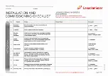
Page 49: ...llation completion Record the total power of the PV modules Switch off the DC and AC distribution unit connect DC to PV terminals of inverter and connect AC to AC terminals of inverter Ensure proper polarity and cable size Torque to specifications Measure and record DC voltage Ensure voltage and polarities are correct Confirm the voltages are within 5 tolerance to what was tested Measure and recor...

Page 50: ...id green and the Fault LED is off CSI xx KTL GS 1 Switch the grid supply main Switch AC ON irst 2 Switch the DC switch ON If the voltages of PV arrays are higher than start up voltage the inverter will turn on The red LED power will be continuously lit 3 When both the DC and the AC sides supply to the inverter it will be ready to generate power Initially the inverter will check both its internal p...

Page 51: ...ication with a unique address for each inverter For maintenance and reference please record the firmware revisions if applicable Record operating parameters of the inverter Verify IEEE1547 or UL1741 setting is selected De rate inverter and attach de rate sticker as required Open and close the DC breaker to conirm whether the inverter reboots and shuts down automatically Installation and commission...

Page 52: ... Number of series connected modules in PV strings Number of PV strings in parallel per MPPT Total System size DC Watts GENERAL COMMENTS I OBSERVATIONS www canadiansolar com S1 CanadianSolar 3 PHASE STRING INVERTERS KTL SERIES Warning This checklist is not a replacement for the user manual Please read the user manual prior to inverter site selection and installation Note site typical arrangements a...

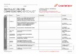
Page 53: ...lar com S1 CanadianSolar 3 PHASE STRING INVERTERS KTL SERIES Warning This checklist is not a replacement for the user manual Please read the user manual prior to inverter site selection and installation 22 23 24 25 26 27 28 29 30 31 32 33 34 35 36 37 38 39 40 41 42 COMPANY_______________________________________________________ DATE _______________________________________________________________ Pl...

Reviews: