K E L O W N A T P 5 0 0
K E L O W N A T P 5 0 0
(8)
(9)
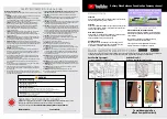
Filling up your Spa
IMPORTANT:
Before filling the spa, it is important to read and
understand the water chemistry section of this manual. Do not
proceed until the water chemistry section is understood and the
source water is tested.
Verify that the spa is in the desired final location. Once filled, the
spa cannot be moved without draining.
Follow these filling instructions to avoid damage to the spa pumps:
1. Leave power to the spa off until spa is completely filled.
2. Never leave an unfilled spa exposed to direct sunlight with
out the Spa Cover installed. Resulting damage such as
bubbles and wrinkles in the spa shell and fading of the jet
faces is not covered by the manufacturer’s warranty.
3. Never operate spa pump without water because this could
result in permanent pump and/or heater damage which is
not covered by the manufacturer’s warranty.
4. Remove all warning labels from spa shell.
6. Remove the filter lid, basket and filter cartridge.
7. Inspect all Jets (shipping may cause jets to become loose
or detached). Check to see that the black Drain Valve
(located to the left or right of the front access panel) is closed.
IMPORTANT:
Follow the next steps closely to prevent damage to
the Spa Pump.
Filter Type:
Glacier Microban Filter Set SKU: KA-10082
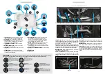
8. Insert garden hose or other clean water source directly into
filter housing. Push hose pipe into filter housing until it stops.
Fill up to top of the skimmer Secure hose placement and
turn on water. Filling the spa through the filter housing
prevents an air lock from occurring in the spa pump, which is
an air pocket preventing the flow of water through the pump.
Permanent damage caused by running the pump with an air
lock or without water) is not covered by the manufacturer’s
warranty.
9. Check for leaks! Although spas are fully checked at the
factory, shipping and delivery might cause a leak.
10. Before power is applied familiarise yourself with the spa
control operations.
11. Turn water off and remove hose.
12. Reinstall filter cartridge, basket and filter lid.
13. Add start-up Chemicals after power is turned on.
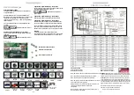
Installation: Electrical power requirements
Power connections
Single Phase (A)
is the normal wiring configuration for most household electrical installations (3 wires: live, neutral and earth). If however you
have insufficient Amps you will need to use other connection (see below).
2 Single Phase connection (B)
is used in circumstances where the
power supply is limited and where you need more Amps.
3 Phase (C)
is used in certain areas of Europe where 3 Phase power is available and
the installation warrants it.
NOTE:
Canadian Spa Company requires that the electrical installation of your hot tub is carried out by a
professionally licensed electrician and that all local electrical and building codes are adhered to.
A.) Single Phase connection (Most common):
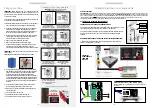
CONNECTING HOT TUB TO RCD AND CONSUMER PANEL:
• All hot tubs must be wired with the appropriate sized wiring. Failure to do so will
cause equipment damage and will not be covered by your warranty
• All hot tubs must be protected with a appropriately sized RCD (Residual Current
Device) in the consumer panel. Have your electrician verify using the diagram
opposite.
ADDITIONAL ITEMS NEEDED TO HELP COMPLETE ELECTRICAL CONNECTION:
1. RCD Breaker, 2. Electrical cable (check length and width for amperage and
distance), 3. Cable gland. 4. Tidy clips
Consumer panel
RCD Breaker
Hot tub control box
11
Manufactured under one or more of these patents. U.S. Patents: 5332944, 5361215, 5550753, 5559720, 5,883,459, 6253227, 6282370, 6590188, 6976052, 6965815, 7030343, 7,417, 834 b2,
Canadian Patent: 2342614, Australian patent: 2373248 other patents both foreign and domestic applied for and pending. All material copyright of Balboa Water Group.
42217 C
K4
F4 3A SLO-BLOW
J25 J31
J26 J30
115V 115V
230V
F3 0.3A SLO-BLOW
J25=HTR1
J26=HTR2
J27=HTR3
J30=TEST
J31=CE
HTR
SEL
F7 10A 250VAC
F2 10A 250VAC
J44
3
TB1
J15
ON
10
S1
K5
K1
K3
T1
K2
K8
LIGHT
GND
J33
J32
J9
2
K6
4
3
2
1
J45
J110
J79 J54
J72 J42 J3
J37 J4 J1
J61
J47
J77 J75 J78
J36
J60
J46
J38
J39
J111
J53 J58
J11
J41
J48
J6
J7
J49
J19
J50
J13
J12 J88 J62
F6 30A
F8 30A
J56 J57 J55
J59
J51 J52 J98
J10
J81
J20
J18
J43
CIRC PUMP
OZONE
A/V HOT
PUMP 1
J5
AUX
J8
AUX
J40
REMOTE
J35
MAIN
J34
MAIN
J109
J27
J91
J22
J23
SERIAL
J29
VAC
J28
AUX
FRZ
J17
J16
J101
J108
J24
J107
K12
K7
AUX**
1
2
3
4
K9
5
4
J31=CE
HTR
SEL
TB1
K2
5
0
9 4
J72 J42
J37 J4
1
7 5 8
J36
J60
J 6
J
J
J53
J41
J12
F6 30A
J56 J57 J55
J59
J51 J52
PUMP 1
1
2
3
4
Spa System Box
1
2
3
4
Test for Voltages by placing
probes on these locations
J32 J33
K4
3
2
1
A.) Single Phase connection (most common):
Single Phase (live 1, neutral 1, live 2, neutral 2, ground)]
230VAC, 50/60Hz, 2þ, 16A, (Circuit Breaker rating = 20A max each
phase line.)
11
Manufactured under one or more of these patents. U.S. Patents: 5332944, 5361215, 5550753, 5559720, 5,883,459, 6253227, 6282370, 6590188, 6976052, 6965815, 7030343, 7,417, 834 b2,
Canadian Patent: 2342614, Australian patent: 2373248 other patents both foreign and domestic applied for and pending. All material copyright of Balboa Water Group.
42217 C
K4
F4 3A SLO-BLOW
J25 J31
J26 J30
115V 115V
230V
F3 0.3A SLO-BLOW
J25=HTR1
J26=HTR2
J27=HTR3
J30=TEST
J31=CE
HTR
SEL
F7 10A 250VAC
F2 10A 250VAC
J44
3
TB1
J15
ON
10
S1
K5
K1
K3
T1
K2
K8
LIGHT
GND
J33
J32
J9
2
K6
4
3
2
1
J45
J110
J79 J54
J72 J42 J3
J37 J4 J1
J61
J47
J77 J75 J78
J36
J60
J46
J38
J39
J111
J53 J58
J11
J41
J48
J6
J7
J49
J19
J50
J13
J12 J88 J62
F6 30A
F8 30A
J56 J57 J55
J59
J51 J52 J98
J10
J81
J20
J18
J43
CIRC PUMP
OZONE
A/V HOT
PUMP 1
J5
AUX
J8
AUX
J40
REMOTE
J35
MAIN
J34
MAIN
J109
J27
J91
J22
J23
SERIAL
J29
VAC
J28
AUX
FRZ
J17
J16
J101
J108
J24
J107
K12
K7
AUX**
1
2
3
4
K9
5
4
J31=CE
HTR
SEL
TB1
K2
5
0
9 4
J72 J42
J37 J4
1
7 5 8
J36
J60
J 6
J
J
J53
J41
J12
F6 30A
J56 J57 J55
J59
J51 J52
PUMP 1
1
2
3
4
Spa System Box
1
2
3
4
Test for Voltages by placing
probes on these locations
J32 J33
K4
3
2
1
ELECTRICAL
REQUIREMENTS
FOR WIRED
HOT TUBS
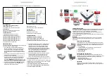
1.
Inset closed position.
(Push in to release internal
O-Ring seal prior to Step #2)
3.
Full extended closed
position (attach garden hose in
the full extended closed
position).
5.
Open position for draining
(turn hose and fitting ¼ turn
counter clockwise and pull out to
full extended closed position).
7.
With replaced cap screwed
on, turn ¼ turn clockwise and
push in all the way to inserted
closed position.
2.
Extended closed position )pull
out to fully extended position
and remove cap); place cap in
safe place.
4.
Open position for draining
(turn hose and fitting ¼ turn
clockwise and insert ½ way to
open position for draining).
6.
Full closed extended
position (remove hose and
replace cap).
8.
Closed inserted position.
Draining your Spa/Using drain valve
IMPORTANT:
Before draining your spa shut off the
electrical breaker connected to the spa.
Accessing your spa controls
To access the
Control Pack undo
the 3 screws on
both panel strips
Water Fill level


