background image

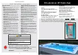
S T   L A W R E N C E   2 0   S W I M   S P A

S T   L A W R E N C E   2 0   S W I M   S P A

(4)

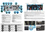
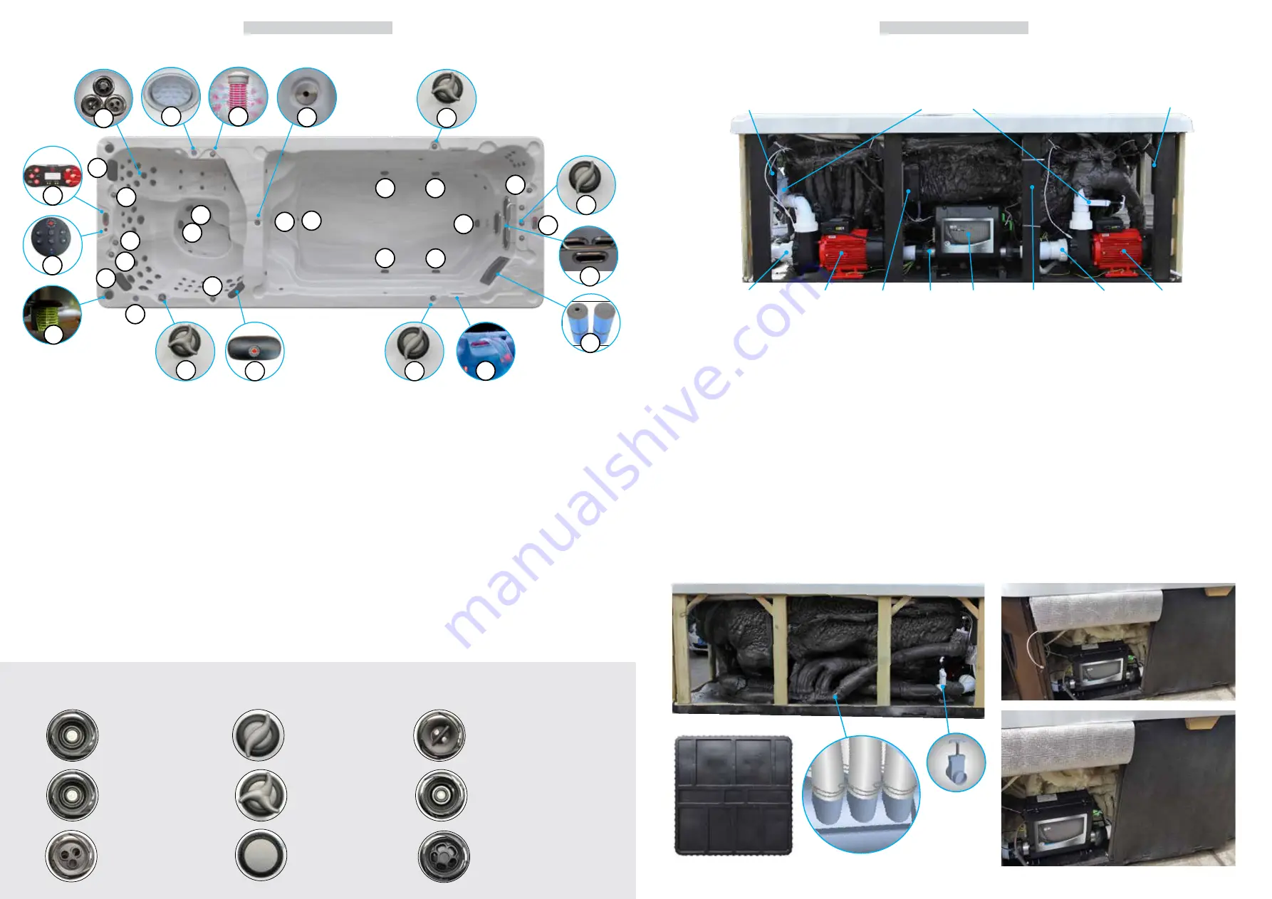
1.   FILTER BASKET:

 Assembly that holds the filter cartridge (Note:   


configurations may differ from model to model).

2.   SPA PILLOW:

 To rest you head and neck (replaceable).

3.  AIR CONTROLLER

: These are located around the top of your spa.  


Increase or decrease the force of your jets by opening or closing  


the air control valves.

4.   ILLUMINATED CUP HOLDER:

 Placeholder for drinking receptacle.

5.  WATERFALL ON/OFF VALVE: 

Located on top rail of spa used to   


adjust the waterfall flow. 

6.


LED ILLUMINATED SPEAKER: 

Audio speaker system


for playing  


music from an MP3 device 

7.   AROMATHERAPY: 

A small canister that holds scented beads and  


works in conjunction with the air control system to create an    


aromatic experience.

8.   AUDIO VOLUME CONTROL: 

Allows control of functions from    

       within the Swim Spa connected Bluetooth (6 button control). 

9.


TOPSIDE CONSOLE: 

Button pad and temperature display 


panel located on the top of the spa into which various 


commands, control sequences and options for operating the 


spa can be input. User can set temperature, filtration cycle and   


heating mode through the console. 

10.


SUCTION FITTING:

 Located at the bottom of the spa, used to    


return water back into the filter and pump system. 

11.


JET (VARIOUS):

 Device that ejects air and water, creating water  


movement in the spa. Adjustable, directional, rotational and  


 interchangeable.

12. WATERFALL & PERIMETER LIGHTING: 

For a relaxing spa mood.

13.  VACUUM BRAKE: 

Ensures the suction inside the spa is cut off    


immediately if blocked.

14.  LARGE DIVERTER: 

Diverts the flow of water from one jet zone to  

 another.

15.


MAIN


SPA LIGHT

16.  DRAIN OUTLET

17.  SWIM JET AIR CONTROLS

18.  SWIM JETS

19.  TETHER POINT: 

Allows you to tether a swim pole in order to give  


extra resistance when swimming against the flow of the jets.

CONTROL PACK: 

Unit that controls spa operations, containing electronic programming boards, heater and all connections for 

Pump(s), Light(s), Ozone Generation Unit and Topside Console. Also referred to as ‘Spa Pack’ or ‘Controller’.

HEATER:

 Electrical resistance device located in the Spa Controller containing the heating element and 2 temperature sensors. 

The flow through heater heats the spa’s water as it flows across the heating element. Heaters are available in several wattages.

MASSAGE PUMP: 

Electro-mechanical device to move water, consisting of a wet end and a motor.

OZONE /UV GENERATOR:

 Device that generates ozone to aid in maintaining water quality. Generates Ozone and UV to help eliminate 

organic material such as body oils, dead skin cells and hair.

DRAIN VALVE: 

Valve located on the outside of spa cabinet used to drain water from the spa. A garden hose can be attached to the 

drain valve.

EQUIPMENT BAY:

 Located under the spa shell covered by access panels that houses the spa controller and equipment.

SLICE VALVE: 

Two-position (open or closed) sliding valve, used to cut off water flow which allows for service to be performed on 

the spa equipment without the need to drain the spa. Slice valve operations: up for open, down (toward the valve body) for closed.

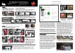
Swim Spa equipment side 

LED Pop-up speaker

Slice valves

LED Pop-up speaker

2.5” Pump 

union

2.5” Pump 

union

Control 

pack

Ozone

Generator

Pump 1

Pump 2

MP3 

Amplifier

Heater

(5)

Swim Spa side view

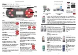
2.25” Twin Roto jet

Adjustable and interchangeable jet spins 

and pulsates. The jet can be removed by 

turning it counter-clockwise. To replace the 

jet push inward and clockwise until it clicks 

into place.

3” Directional jet

Adjustable and interchangeable jet features 

a directional nozzle. The jet can be removed 

by turning it counter-clockwise. To replace 

the jet push inward and clockwise until it 

clicks into place.

3” Massage jet

Rotational and interchangeable jet which 

spins to deliver a soothing massage. The jet 

can be removed by turning it counter-

clockwise. To replace the jet push inward 

and clockwise until it clicks into place.

2.25” Directional jet

Adjustable and interchangeable jet features a 

directional nozzle. The jet can be removed by 

turning it counter-clockwise. To replace the 

jet push inward and clockwise until it clicks 

into place.

5” (Jumbo) Directional jet


Adjustable and interchangeable jet features a 

directional nozzle. The jet can be removed by 

turning it counter-clockwise. To replace the jet 

push inward and clockwise until it clicks into 

place.

5” Massage jet 

Rotational and interchangeable jet features an 

internal spinner to deliver a low pressure sooth-

ing massage. The jet can be removed by turning 

it counter-clockwise. To replace the jet push 

inward and clockwise until it clicks into place.

Air Controller

These are located around the top of 

your spa. Increase or decrease the 

force of your jets by opening or closing 

the air control valves.

Aroma basket cap

Open cap to place aromatherapy 

beads. Close after use. 


Waterfall control 

Located on the topside of the spa, 

this valve adjusts water flow to the 

waterfall.

HOW JETS WORK

Air is mixed with the water by using the air controls to create massage(s) of varying degrees. Water flow is adjusted by simply turning 

the outer face of the full sized jets. Our Swim Spas have a combination of pulsating, rotating, and directional adjustable jets.


14

11

1

3

17

18

7

5

9

19

12

6

8

10

10

10

10

3

3

3

3

4

3

2

2

10

10

10

4

2

9

15

16

Summary of Contents for St Lawrence 16' Swim Spa KS-10006

Page 1: ... W R E N C E 2 0 S W I M S PA St Lawrence 20 Swim Spa Owners Manual 594 x 228 x 137 cm 234 x 90 x 54 KS 10006 For Service Support please contact us anytime support canadianspacompany com canadianspacompany com ...

Page 2: ...onths to make sure that the unit is operating properly 14 CAUTION Do not operate audio video controls while inside the spa 15 Installation of the spa for other than a residential dwelling will result in voiding the manufacturer s warranty 16 Do not bring any object into the spa that could damage the spa shell 17 Never insert any object into any opening 18 WARNING Do not sit on the spa cover or pla...

Page 3: ...body oils dead skin cells and hair DRAIN VALVE Valve located on the outside of spa cabinet used to drain water from the spa A garden hose can be attached to the drain valve EQUIPMENT BAY Located under the spa shell covered by access panels that houses the spa controller and equipment SLICE VALVE Two position open or closed sliding valve used to cut off water flow which allows for service to be per...

Page 4: ...en please ask before ground construction and the delivery of your spa Your spa must be sited on a solid flat level base which is the same size or larger than the spa The base can be either a 10 15cm concrete slab or suitably strengthened timber decking or existing patio area assuming it has suitable foundations of hardcore Whatever base area is chosen it must be of suitable load bearing capacity P...

Page 5: ...s To access the Control Pack undo the 4 screws on both panel strips Installation Electrical power requirements Power connections Single Phase A is the normal wiring configuration for most household electrical installations 3 wires live neutral and earth If however you have insufficient Amps you will need to use other connection see below 2 Single Phase connection B is used in circumstances where t...

Page 6: ...e The last number in the sequence is the incoming power meter which can be used to verify that the spa is wired correctly 2 The spa begins an automatic priming routine which will last 6 minutes Pr is on the LED display 3 The priming routine will automatically run each spa pump to prime When the Pr is displayed press any PUMP button to prime that pump or wait for the priming routine to turn on the ...

Page 7: ...and it will tell you what to add and how much KA 10052 Spa Flush Annually flush the spa to remove bio film that has attached to the interior of the spa pipes KA 10164 2 Pump Control System TP600 Initial Start up When your spa is first activated the display will do a count sequence of M100 L232 V52 1 3 afterwards a message will display RUN PUMPS PURGE AIR on Priming Mode TEMP DOWN Decrease Temperat...

Page 8: ...ncing an air lock This normal occurrence can be easily corrected by loosening the plumbing union on the suction side of the Jet or Pump until water flows into the pump and all air is expelled PRESS BUTTONS SLOWLY FOR FIRST RUN WHEN STARTING UP ONCE PR EXITS SET TEMPERATURE ON SPA Airlock warning messages If you receive any of these error messages on your spa you could have an airlock FLO How to re...

Page 9: ...nt See common water problem section Settings 2 x Pumps standard Simple Options Press Menu Temp Up then Light button until you reach the mode you require TEMP Temp Up button until arrow is either pointing up or down Arrow up will maintain heat Arrow down will drop the temp by 10 degrees Menu Temp Up then Light to select MODE Temp Up button press until either Ready or Rest is displayed Ready maintai...

Page 10: ...mentarily turning the pump off and on will help it to prime Do not do this more than 5 times If the pump will not prime shut off the power to the spa and call for service Important A pump should not be allowed to run without priming for more than 2 minutes Under NO circumstances should a pump be allowed to run without priming beyond the end of the 4 5 minute priming mode Doing so may cause damage ...

Page 11: ...et but since the spa started at noon the filter cycles will run as programmed Flip Invert Display Restricting Operation The control can be restricted to prevent unwanted use or temperature adjustments Locking the panel prevents the controller from being used but all automatic functions are still active Locking the Temperature allows Jets and other features to be used but the Set Temperature and ot...

Page 12: ... the filter Hold Mode will last for 1 hour unless the mode is exited manually Drain Mode Some spas have a special feature that allows a pump to be employed when draining the water When available this feature is a component of Hold Mode Drain Mode will time out with Hold Mode Sub Menu Detail User Preferences 05 15 09 Preferences F C Temp Display Change the temperature between Fahrenheit and Celsius...

Page 13: ... water in the heater to start it The spa is shut down for 15 min Press any button to reset the heater start up See Flow Related Checks below Heater is Dry MO27 There is not enough water in the heater to start it The spa is shut down After the problem has been resolved you must press any button to reset and restart heater start up See Flow Related Checks RUN PMP5 PURG AIR C TOO COLD WATR TOO HOT CH...

Page 14: ... Residual Current Device RCD is an important safety device and must be tested on a regular basis to verify its reliability Every user should be trained to safely test the RCD associated with the Swim Spa installation An RCD will have a TEST and RESET button on it that allows a user to verify proper function Warning If freezing conditions exist a RCD should be reset immediately or spa damage could ...

Page 15: ...ar maintenance or protection is essential Canadian Spa Co warrants the cover for the period of two 2 years Defects caused by misuse or insufficient care are not covered by the warranty TERMS CONDITIONS AND LIMITATIONS Any defect or damage caused by installation alteration or repair by anyone who is not an employee of Canadian Spa Co or authorised service technician is not covered by the Warranty T...

Reviews: