
| 12
EN-Rev IM/GN-EN/1.0 Copyright © January, 2023. CSI Solar Co., Ltd.
areas (i.e. IEC 62930: 2017 approved), with proper
insulation which is able to withstand the maximum possible
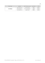
system open-circuit voltage. For CS7N and CS7L modules,
Canadian Solar recommends the use of a copper wire of at
least 6 mm
2
(10AWG) section.
Only copper conductor material should be used. Select a
suitable conductor gauge to minimize voltage drop and
ensure that the conductor ampacity complies with local
regulations (i.e. NEC 690.8(D)).
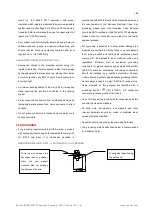
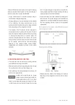
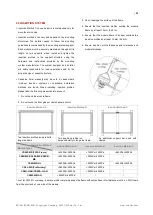
CABLE AND CONNECTOR PROTECTION
Secure the cables to the mounting system using UV-
resistant cable ties. Protect exposed cables from damage
by taking appropriate precautions (e.g. placing them inside
a metallic raceway like EMT conduit). Avoid exposure to
direct sunlight.
A minimum bending radius of 60 mm (2.36 in) is required
when securing the junction box cables to the racking
system.
Protect exposed connectors from weathering damage by
taking appropriate precautions. Avoid exposure to direct
sunlight.
Do not place connectors in locations where water could
easily accumulate.
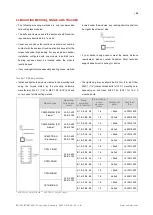
5.2 GROUNDING
For grounding requirements in North America, a module
with exposed conductive parts is considered to comply with
UL 61730 only when it is electrically grounded in
accordance with both the instructions presented below and
the requirements of the National Electrical Code. Any
grounding means used with Canadian Solar modules
should be NRTL certified to UL 467 and UL 2703 standards.
Please consult our technical service team for the formal
approval process.
For grounding requirements in other areas, although the
modules are certified to Safety Class II, we recommend
them to be grounded and that module installation should
comply with all applicable local electrical codes and
regulations. Minimum size of equipment grounding
conductors for ground raceway and equipment from NEC
690.8(D) should be considered. Grounding connections
should be installed by a qualified electrician. Connect
module frames together using adequate grounding cables:
we recommend using 4-14 mm² (AWG 6-12) copper wire.
Holes provided for this purpose are identified with a
grounding symbol
(IEC 61730-1). All conductive
connection junctions must be firmly fixed.
Do not drill any extra ground holes for convenience as this
will void the module’s warranty.
All bolts, nuts, flat washers, lock washers and other
relevant hardware should be made of stainless steel,
unless otherwise specified.
Canadian Solar does not provide grounding hardware.
The grounding method described below is recommended
for Canadian Solar.
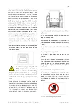
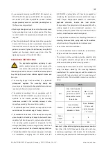
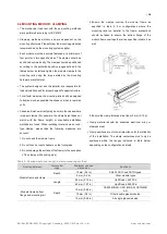
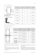
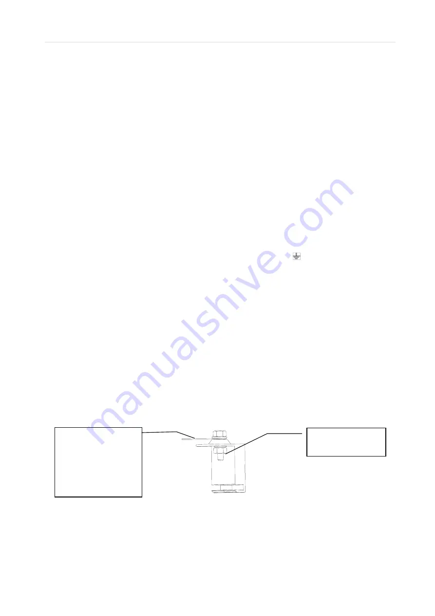
GROUNDING METHOD: BOLT + TOOTHED NUT + CUP WASHER.
To fix the wire between the
flat washer and cup washer,
place
the
cup
washer
(concave side up) between
the frame and the wire.
Then tighten the bolt using
the toothed nut.


