| 13
EN-Rev IM/GN-EN/1.0 Copyright © January, 2023. CSI Solar Co., Ltd.
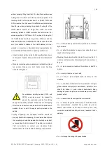
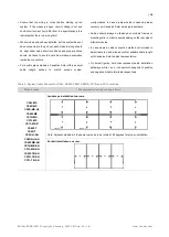
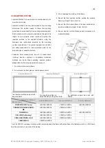
A grounding kit containing an M5 (3/16") SS cap bolt, an
M5 (3/16") SS flat washer, an M5 (3/16") SS cup washer,
and an M5 (3/16") SS nut (with teeth) is used to attach
copper grounding wire to a pre-drilled grounding hole on
the frame (see image above).
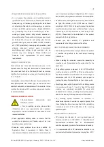
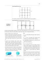
Mounting rail designs should be such to allow easy access
to the grounding holes located on the long side of the frame,
in order to enable the equipment grounding function when
required.
Place the wire between the flat washer and the cup washer.
Ensure that the cup washer is positioned between the
frame and the wire with the concave side up to prevent
galvanic corrosion. Tighten the bolt securely using the SS
toothed nut. A wrench may be used to do this. The
tightening torque is 3-7 Nm (2.2-5.2 ft-lbs).
6 MOUNTING INSTRUCTIONS
The applicable regulations pertaining to work
safety, accident prevention and securing the
construction site must be observed. Workers and
third-party personnel shall wear or install fall arrest equipment.
Any third party need to be protected against injuries and
damages.
The mounting design must be certified by a registered
professional engineer. The mounting design and
procedures must comply with all applicable local codes and
requirements from all relevant authorities.
The module is considered to be in compliance with UL
61730 and IEC 61215/61730 only when the module is
mounted in the manner specified by the mounting
instructions included in this installation manual or when
specially approved by Canadian Solar in writing.
The system designer and installer are responsible for load
calculations and for proper design of support structure.
The mechanical load tests in this manual are only valid
when coupled to mounting and support structures that are
capable of withstanding equal or greater mechanical loads.
The mounting system supplier is responsible for the
strength and stability of the mounting structure, which must
meet the requirements of the relevant design specifications.
The loads described in this manual correspond to test loads.
For installations complying with UL 61730 and IEC
61215/61730, a safety factor of 1.5 should be applied for
calculating the equivalent maximum authorized design
loads. Project design loads depend on construction,
applicable standards, location and local climate.
Determination of the design loads is the responsibility of the
racking suppliers and/or professional engineers. For
detailed information, please follow local structural code or
contact your professional structural engineer.
Use appropriate corrosion-proof fastening materials. All
mounting hardware (bolts, spring washers, flat washers,
nuts) should be hot dip galvanized or stainless steel.
Use a torque wrench for installation.
Do not drill additional holes or modify the module frame.
Doing so will void the module’s warranty.
This manual includes preliminary loading capability data
which might be subject to change, please refer to official
version which will be updated in coming versions.
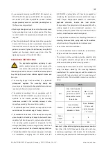
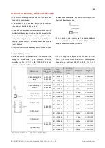
Install and tighten the module clamps to the mounting rails
using the torque stated by the mounting hardware
manufacturer. The system designer and the installer are
responsible for load calculations and for proper design of
support structure. Recommended accessories are shown
below.
Accessory
Model
Bolt
M8 x 1.25-Grade 8.8
(5/16”-18 Grade B7)
galvanized or A2-70
stainless steel coarse
thread bolts.
M6 X 1 (1/4”)
coarse thread
bolts
Washer
2 pcs, thickness
≥
1.5mm and outside
diameters = 16mm
2 pcs, thickness
≥
1.5mm and
outside diameters
= 12-16mm
Spring
washer
8
6
Nut
M8
M6
Note that: 1) M8 and M6 bolt tightening torques must be within
16~20 Nm (11.8~14.75 ft-lbs) and 6~9 Nm (4.5~6.6 ft-lbs),
respectively, depending on bolt classes. For the bolt grade,
the technical guidelines from the fastener suppliers should be


