background image

  | 

EN-Rev IM/GN-EN/1.0 Copyright © January, 2023. CSI Solar Co., Ltd.


www.csisolar.com


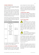
to  +40  °C. The  98th-percentile  of  the  module  operational 

temperature  should  be  of  70  °C  or  lower  under  any 

mounting  conditions.


If  the  application  where  the  98th-

percentile of the module operational temperature of 80 °C 

is needed, you have to specially select IEC 63126 Level 1 

certified BOMs.


This environmental temperature range encompasses many 

locations  and  installation  methods. Annex A  provides  the 

reader with modelled PV module temperature examples, at 

the  98th-percentile  depending  on  the  different  worldwide 

locations. 


Please  consult  the  Canadian  Solar  technical  support 

department for more information on the use of modules in 

special climates, such as an altitude greater than 2000 m, 

heavy snow, severe hail storm, hurricane, etc. 
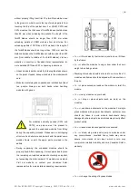
 

Do  not 

install  modules  near  open  flames  or  flammable 

materials. 


Do  not


immerse  modules  in  water  or  constantly  expose 

modules to water (either fresh or salt, i.e. from fountains, 

sea spray). 


Exposing  modules  to  salt  (i.e.  marine  environments)  or 

sulfur  (i.e.  sulfur  sources,  volcanoes)  incurs  the  risk  of


module corrosion.     


Do  not  expose  modules  and  their  connectors  to  any 

unauthorized  chemical  substances  (e.g.  oil,  lubricant, 

pesticide, etc.), as modules may incur damages. 


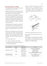
Canadian  solar  modules  have  passed  salt  mist  corrosion 

resistance test according to IEC 61701, but the corrosion 

may still occur on where the modules frame is connected 

to the bracket or where the grounding is connected. Should 

the installation location be near the ocean, Canadian solar 

recommends stainless steel or aluminum materials be used 

in the areas with direct contact with the PV modules, and 

the  connection  point  should  be  protected  with  anti-

corrosion measures. For more information, please contact 

Canadian solar technical support team. 

INSTALLATION REQUIREMENTS


Ensure that the module meets the general technical system 

requirements. 


Ensure that other systems components do not damage the 

module mechanically or electrically. 


Modules  can  be  wired  in  series  to  increase  voltage  or  in 

parallel to increase current. To connect modules in series, 

connect the cables from the positive terminal of one 

module


to the negative terminal of the next module. To connect in 

parallel,  connect  the  cables  from  the  positive  terminal  of 

one module to the positive terminal on the next module. 


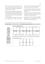
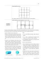
The quantity of bypass diodes in the module junction box 

provided may vary depending on the model series. 


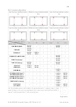
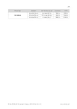
Only connect the quantity of modules that corresponds to 

the  voltage  specifications  of  the  inverters  used  in  the 

system.  In  addition,  modules  must  not  be  connected 

together  to  create  a  voltage  higher  than  the  maximum 

permitted system voltage stated on the module nameplate, 

even  under  the  worst  local  temperature  conditions  (see 

Table  1  for  the  correction coefficients  that  apply  to  open-

circuit voltage).     


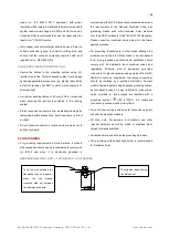
A  maximum  of  two  strings  can  be  connected  in  parallel 

without using an over-current protection device (fuses, etc.) 

incorporated  in  series  within  each  string.  Three  or  more 

strings can be connected in parallel if an appropriate and 

certified over-current protection device is installed in series 

within each string. And it shall be ensured in the PV system 

design  that  the  reverse  current  of  any  particular  string  is 

lower  than  the  module  maximum  fuse  rating  at  any 

circumstances. 


Only modules with similar electrical parameters should be 

connected  in  the  same  string  to  avoid  or  minimize 

mismatch effects in arrays. 


To minimize risk in the event of an indirect lightning strike, 

avoid  forming  loops  with  the  wiring  when  designing  the 

system. 


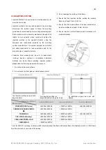
Modules should be safely fixed to bear all expected loads, 

including wind and snow loads.   


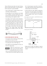
A minimum clearance of 6.5 mm (0.25 in) between modules 

is  required  to  allow thermal  expansion  of  the  frames  and 

modules. 

OPTIMUM ORIENTATION AND TILT 


To maximize the annual yield, please calculate the optimum 

orientation  and  tilt  for  PV  modules  in  that  specific 

Summary of Contents for CS6R-MS Series

Page 1: ...For professional use only INSTALLATION MANUAL OF PHOTOVOLTAIC MODULE...

Page 2: ...NPACKING AND STORAGE 5 5 MODULE INSTALLATION 7 5 1 MODULE WIRING 9 5 2 GROUNDING 12 6 MOUNTING INSTRUCTIONS 13 6 1 MOUNTING METHOD BOLTING 14 6 2 MOUNTING METHOD CLAMPING 16 6 3 INSERTION SYSTEM 23 6...

Page 3: ...nguage versions of this document the English version shall prevail Please refer to our product lists and documents published on our website at www csisolar com as these lists are updated on a regular...

Page 4: ...C No 793 93 and Commission Regulation EC No 1488 94 as well as Council Directive 76 769 EEC and Commission Directives 91 155 EEC 93 67 EEC 93 105 EC and 2000 21 EC the REACH Regulation we inform you t...

Page 5: ...x 1 25 x Max 1 175 Impp ImppSTC Impp the highest 3 hour current average resulting from the simulated local simultaneous irradiances on the front and rear sides of the PV array accounting for elevation...

Page 6: ...anti tipping structure Such structure can be built with the pallet s own wooden frame or with the spare parts provided in the pallets During unpacking the unpacked modules should be properly fixed Aft...

Page 7: ...ation Class A equivalent to Safety Class II requirements Modules rated under this class should be used in systems operating at voltage above 50V or power above 240W where general contact access is ant...

Page 8: ...general technical system requirements Ensure that other systems components do not damage the module mechanically or electrically Modules can be wired in series to increase voltage or in parallel to in...

Page 9: ...A module can be considered to be unshaded if its entire surface is free from shading all year round including on the shortest day of the year For optimizing the power generation of the rear side of b...

Page 10: ...dian Solar sales representative Cables should always be fastened on module frames or mounting rails in order to avoid shading on the rear side of bifacial modules In case where a cable connection meth...

Page 11: ...g connector endcaps should be taken to avoid moisture and dust penetrating into the connector If end caps are present on un mated connectors carefully remove by hand the end caps before connecting the...

Page 12: ...structions presented below and the requirements of the National Electrical Code Any grounding means used with Canadian Solar modules should be NRTL certified to UL 467 and UL 2703 standards Please con...

Page 13: ...standing equal or greater mechanical loads The mounting system supplier is responsible for the strength and stability of the mounting structure which must meet the requirements of the relevant design...

Page 14: ...ill lead to more severe deflection 6 1 MOUNTING METHOD BOLTING The mechanical load test with these mounting methods were performed according to IEC 61215 Modules should be bolted to supporting structu...

Page 15: ...3200Pa 5400Pa 3200Pa CS6W MS CS7L MS CS7N MS 5400Pa 2400Pa CS6W T Preliminary 5400Pa 2400Pa CS6R T Preliminary 5400Pa 2400Pa 5400Pa 2400Pa CS6R H AG CS6RA H AG 5400Pa 2400Pa 3600Pa 2400Pa CS6W MB AG...

Page 16: ...When installing inter modules or end type clamps please take the following measures into account 1 Do not bend the module frame 2 Do not touch or cast shadows on the front glass 3 Do not damage the su...

Page 17: ...0 100 100 600 250 550 400 500 CS6W MS CS7L MS 300 600 400 500 CS7N MS 300 600 450 550 CS6W T Preliminary 400 500 CS6R T Preliminary 300 400 CS6L MS Preliminary 400 500 CS6R H AG 400 550 400 500 CS6RA...

Page 18: ...long side frame Module Types Max Mechanical Load Pa 1600 1600 2800 2400 3200 2400 3600 2400 4000 2400 4000 3200 5400 2400 A1 Range mm CS6R MS CS6RB MS 200 600 200 300 CS6RA MS 200 400 CS6R MS HL 100 6...

Page 19: ...de of frame and rails perpendicular to the long side frame Module Types Max Mechanical Load Pa 5400 2400 5400 2800 6000 3600 6000 4000 8100 5000 A3 A5 Range mm CS6R MS CS6RA MS CS6RB MS 80 380 CS6R MS...

Page 20: ...0 100 300 CS6R H AG 400 600 200 250 CS6W MB AG F42 Frames 600 700 200 250 with 35mm height frame 6 2 7 Four clamps mounting on short side of frame Module Types Max Mechanical Load Pa 1200 1200 2200 22...

Page 21: ...r single glass monofacial modules Note that clamp overlap length of 40mm or 1 50 in when uplift load 2400 Pa is allowed Landscape installation clamping on long side frame Modyle Type Max Span Max Cant...

Page 22: ...Solar Co Ltd www csisolar com Modyle Type Max Span Max Cantilever length Downforce Uplift CS6R MS HL 48 inches 1 22 m 16 inches 0 41 m 1800 Pa 1800 Pa 32 inches 0 81 m 10 7 inches 0 27 m 1800 Pa 1800...

Page 23: ...ule frame 2 Do not touch the front glass or cast shadows onto it 3 Do not damage the surface of the frame 4 Ensure that the insertion profiles overlap the module frame by at least 10 mm 0 39 in 5 Ensu...

Page 24: ...le clamps to the mounting rails using the torque stated by the mounting hardware manufacturer M6 X 1 1 4 or M8 X 1 25 5 16 bolt and nut are used for this bolting method The tightening torques should b...

Page 25: ...6 1900 1900 B1 B2 B3 B4 16 2600 2200 CS6W TB AG A1 A3 400 B1 B3 790 B1 B2 A3 A4 16 1900 1900 B1 B2 B3 B4 16 2600 2200 CS6W MB AG F42 Frame A1 A3 400 B1 B3 790 B1 B2 A3 A4 16 1800 1600 B1 B2 B3 B4 16 2...

Page 26: ...the potential electric shock hazard Cracked or broken modules represent an electric shock hazard due to leakage currents and the risk of shock is increased when modules are wet Before cleaning thoroug...

Page 27: ...n Solar technical support department for information on the use of cleaning solutions and loading specifications OPERATION PREPARATION Noticeable dirt must be rubbed away by gentle cleaning implement...

Page 28: ...to roof array size array spacing and anti nesting features as it may allow a more efficient ventilation The graphics below from IEC 63126 show this influence the maps presented here are a general guid...

Page 29: ...29 EN Rev IM GN EN 1 0 Copyright January 2023 CSI Solar Co Ltd www csisolar com Figure A 3 Spatial distribution of the K ppen climate types for the period from 1901 to 2010...

Page 30: ...electrical parameters and limitations of the MLPE devices and the Canadian Solar modules are suitable for one another Failure to comply with these instructions will void the Canadian Solar warranty I...

Page 31: ...their distance from the coastline Different coastal land areas are defined according to how far away from the coastline they are Canadian Solar generally classifies seashore PV installations according...

Page 32: ...n These washers are made in a process called explosion welding Concerning insulation gaskets we recommend mica laminate or other silicone or fluoride based insulating materials C 2 3 ANTI CORROSION ME...

Page 33: ...eas Process specifications for the different components must comply with relevant international anti corrosion standards Minimum coating thicknesses for hot dip galvanized and anodizing oxide componen...

Page 34: ...CSI Solar Co Ltd www csisolar com of any kind including but not limited to bodily harm injury and damage to property as a result of handling modules installing systems or compliance or non compliance...

Page 35: ...Copyright January 2023 CSI Solar Co Ltd www csisolar com AMENDED EDITIONS AND DATES Rev 1 0 integrated version first release in January 2023 CSI Solar Co Ltd 199 Lushan Road SND Suzhou Jiangsu China...

Reviews: