background image

  | 31 

EN-Rev IM/GN-EN/1.0 Copyright © January, 2023. CSI Solar Co., Ltd.


www.csisolar.com


ANNEX C: COASTAL AREA ANTI-CORROSION INSTALLATION GUIDELINES 

C.1.0: GENERAL INFORMATION 


According  to  the  specific  conditions  stipulated  in  the 

Canadian  Solar  installation  manual  and  general  warranty 

statement,  Canadian  Solar  PV  modules  are  not  allowed 

install in coastal areas. Coastal areas state that the places 

located within 100m of the defined coastline.   


This  annex  has  been  created  to  facilitate  approval  for 

customer PV installations located within 20 m and 100 m of 

the coastline. It lays down general requirements to ensure 

that Canadian Solar PV modules are installed properly and 

reliably in coastal areas, which include but are not limited 

to  relevant  anti-corrosion  principles  for  both  the  modules 

and associated mounting systems. This annex summarizes 

the  key  technical  requirements  stipulated  by  well-known 

international  standards  and  explains  how  they  apply  to 

photovoltaic systems.   


Please  read  this  annex  carefully  and  strictly  follow  any 

relevant  instructions  prior  to  installing  Canadian  Solar 

modules  in  coastal  areas.  Failure  to  follow  these 

instructions and other general anti-corrosion principles may 

result  in  corrosion  damage  to  the  photovoltaic  modules 

and/or  their  racking  systems,  and  will  void  the  Canadian 

Solar limited product and performance warranty. For further 

inquiries, please contact our customer service department 

or our local representatives for more information.   


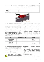
The reliability of photovoltaic modules strongly depends on 

their  distance  from  the  coastline.  Different  coastal  land 

areas  are  defined  according  to  how  far  away  from  the 

coastline  they  are;  Canadian  Solar  generally  classifies 

seashore PV installations according to four different groups: 

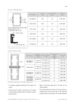
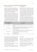
Distance from the coastline   

(X: meters) 

Requirements 

X ≤ 20 m 

Installations are strictly prohibited by Canadian Solar due to concerns over salt-mist 

corrosion. 

20m < X ≤ 100 m 

Installations must comprise Canadian Solar ‟special-anti-corrosion” modules. These 

installations must comply with the instructions listed under sections 

C.2.1/C.2.2/C.2.3/C3.0. 

100m < X ≤ 500 m 

Installation of Canadian Solar ‟special-anti-corrosion” modules is recommended.   

It is recommended to follow the instructions listed under sections 

C.2.1/C.2.2/C.2.3/C.3.0. 

> 500 m 

Please follow section 7.0 


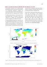
Local conditions strongly influence the salt deposition rate, 

which  is  particularly,  but  not  exclusively,  dependent  on 

specific  regions  and  local  wind  patterns.  Canadian  Solar 

reserves the right to adapt the above definition to individual 

cases. Please contact your local representative to confirm 

which category your PV system falls under. 


The word “coastline” in this manual refers to the area where 

the land meets the sea during high tide. 


In  this  manual,  “distance  to  the  coastline”  refers  to  the 

shortest  distance  between  the  photovoltaic  module  array 

and the coastline. 


Please  consult  the  Canadian  Solar  technical  support 

department  or  your  local  representative  for  more 

information on installing ‟special anti-corrosion” modules.


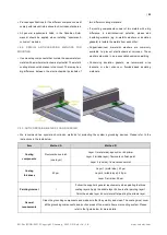
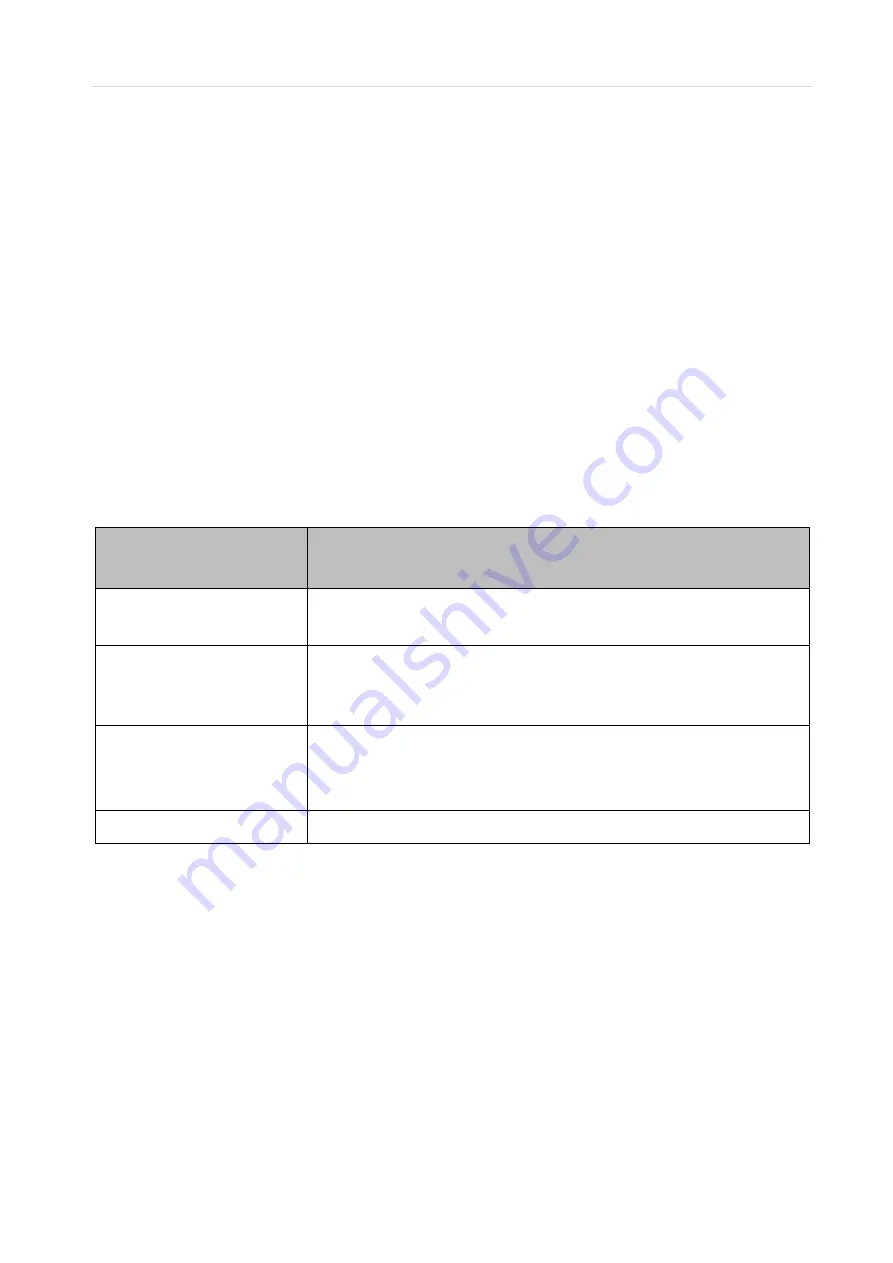
C.2.1: GENERAL ANTI-CORROSION METHODS


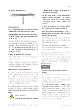
Do not scratch or break the corrosion-resistant coating on 

the modules or mounting systems during installation. 


Do not change the structure of the module, i.e. by drilling 

holes into the module frame. 

Summary of Contents for CS6R-MS Series

Page 1: ...For professional use only INSTALLATION MANUAL OF PHOTOVOLTAIC MODULE...

Page 2: ...NPACKING AND STORAGE 5 5 MODULE INSTALLATION 7 5 1 MODULE WIRING 9 5 2 GROUNDING 12 6 MOUNTING INSTRUCTIONS 13 6 1 MOUNTING METHOD BOLTING 14 6 2 MOUNTING METHOD CLAMPING 16 6 3 INSERTION SYSTEM 23 6...

Page 3: ...nguage versions of this document the English version shall prevail Please refer to our product lists and documents published on our website at www csisolar com as these lists are updated on a regular...

Page 4: ...C No 793 93 and Commission Regulation EC No 1488 94 as well as Council Directive 76 769 EEC and Commission Directives 91 155 EEC 93 67 EEC 93 105 EC and 2000 21 EC the REACH Regulation we inform you t...

Page 5: ...x 1 25 x Max 1 175 Impp ImppSTC Impp the highest 3 hour current average resulting from the simulated local simultaneous irradiances on the front and rear sides of the PV array accounting for elevation...

Page 6: ...anti tipping structure Such structure can be built with the pallet s own wooden frame or with the spare parts provided in the pallets During unpacking the unpacked modules should be properly fixed Aft...

Page 7: ...ation Class A equivalent to Safety Class II requirements Modules rated under this class should be used in systems operating at voltage above 50V or power above 240W where general contact access is ant...

Page 8: ...general technical system requirements Ensure that other systems components do not damage the module mechanically or electrically Modules can be wired in series to increase voltage or in parallel to in...

Page 9: ...A module can be considered to be unshaded if its entire surface is free from shading all year round including on the shortest day of the year For optimizing the power generation of the rear side of b...

Page 10: ...dian Solar sales representative Cables should always be fastened on module frames or mounting rails in order to avoid shading on the rear side of bifacial modules In case where a cable connection meth...

Page 11: ...g connector endcaps should be taken to avoid moisture and dust penetrating into the connector If end caps are present on un mated connectors carefully remove by hand the end caps before connecting the...

Page 12: ...structions presented below and the requirements of the National Electrical Code Any grounding means used with Canadian Solar modules should be NRTL certified to UL 467 and UL 2703 standards Please con...

Page 13: ...standing equal or greater mechanical loads The mounting system supplier is responsible for the strength and stability of the mounting structure which must meet the requirements of the relevant design...

Page 14: ...ill lead to more severe deflection 6 1 MOUNTING METHOD BOLTING The mechanical load test with these mounting methods were performed according to IEC 61215 Modules should be bolted to supporting structu...

Page 15: ...3200Pa 5400Pa 3200Pa CS6W MS CS7L MS CS7N MS 5400Pa 2400Pa CS6W T Preliminary 5400Pa 2400Pa CS6R T Preliminary 5400Pa 2400Pa 5400Pa 2400Pa CS6R H AG CS6RA H AG 5400Pa 2400Pa 3600Pa 2400Pa CS6W MB AG...

Page 16: ...When installing inter modules or end type clamps please take the following measures into account 1 Do not bend the module frame 2 Do not touch or cast shadows on the front glass 3 Do not damage the su...

Page 17: ...0 100 100 600 250 550 400 500 CS6W MS CS7L MS 300 600 400 500 CS7N MS 300 600 450 550 CS6W T Preliminary 400 500 CS6R T Preliminary 300 400 CS6L MS Preliminary 400 500 CS6R H AG 400 550 400 500 CS6RA...

Page 18: ...long side frame Module Types Max Mechanical Load Pa 1600 1600 2800 2400 3200 2400 3600 2400 4000 2400 4000 3200 5400 2400 A1 Range mm CS6R MS CS6RB MS 200 600 200 300 CS6RA MS 200 400 CS6R MS HL 100 6...

Page 19: ...de of frame and rails perpendicular to the long side frame Module Types Max Mechanical Load Pa 5400 2400 5400 2800 6000 3600 6000 4000 8100 5000 A3 A5 Range mm CS6R MS CS6RA MS CS6RB MS 80 380 CS6R MS...

Page 20: ...0 100 300 CS6R H AG 400 600 200 250 CS6W MB AG F42 Frames 600 700 200 250 with 35mm height frame 6 2 7 Four clamps mounting on short side of frame Module Types Max Mechanical Load Pa 1200 1200 2200 22...

Page 21: ...r single glass monofacial modules Note that clamp overlap length of 40mm or 1 50 in when uplift load 2400 Pa is allowed Landscape installation clamping on long side frame Modyle Type Max Span Max Cant...

Page 22: ...Solar Co Ltd www csisolar com Modyle Type Max Span Max Cantilever length Downforce Uplift CS6R MS HL 48 inches 1 22 m 16 inches 0 41 m 1800 Pa 1800 Pa 32 inches 0 81 m 10 7 inches 0 27 m 1800 Pa 1800...

Page 23: ...ule frame 2 Do not touch the front glass or cast shadows onto it 3 Do not damage the surface of the frame 4 Ensure that the insertion profiles overlap the module frame by at least 10 mm 0 39 in 5 Ensu...

Page 24: ...le clamps to the mounting rails using the torque stated by the mounting hardware manufacturer M6 X 1 1 4 or M8 X 1 25 5 16 bolt and nut are used for this bolting method The tightening torques should b...

Page 25: ...6 1900 1900 B1 B2 B3 B4 16 2600 2200 CS6W TB AG A1 A3 400 B1 B3 790 B1 B2 A3 A4 16 1900 1900 B1 B2 B3 B4 16 2600 2200 CS6W MB AG F42 Frame A1 A3 400 B1 B3 790 B1 B2 A3 A4 16 1800 1600 B1 B2 B3 B4 16 2...

Page 26: ...the potential electric shock hazard Cracked or broken modules represent an electric shock hazard due to leakage currents and the risk of shock is increased when modules are wet Before cleaning thoroug...

Page 27: ...n Solar technical support department for information on the use of cleaning solutions and loading specifications OPERATION PREPARATION Noticeable dirt must be rubbed away by gentle cleaning implement...

Page 28: ...to roof array size array spacing and anti nesting features as it may allow a more efficient ventilation The graphics below from IEC 63126 show this influence the maps presented here are a general guid...

Page 29: ...29 EN Rev IM GN EN 1 0 Copyright January 2023 CSI Solar Co Ltd www csisolar com Figure A 3 Spatial distribution of the K ppen climate types for the period from 1901 to 2010...

Page 30: ...electrical parameters and limitations of the MLPE devices and the Canadian Solar modules are suitable for one another Failure to comply with these instructions will void the Canadian Solar warranty I...

Page 31: ...their distance from the coastline Different coastal land areas are defined according to how far away from the coastline they are Canadian Solar generally classifies seashore PV installations according...

Page 32: ...n These washers are made in a process called explosion welding Concerning insulation gaskets we recommend mica laminate or other silicone or fluoride based insulating materials C 2 3 ANTI CORROSION ME...

Page 33: ...eas Process specifications for the different components must comply with relevant international anti corrosion standards Minimum coating thicknesses for hot dip galvanized and anodizing oxide componen...

Page 34: ...CSI Solar Co Ltd www csisolar com of any kind including but not limited to bodily harm injury and damage to property as a result of handling modules installing systems or compliance or non compliance...

Page 35: ...Copyright January 2023 CSI Solar Co Ltd www csisolar com AMENDED EDITIONS AND DATES Rev 1 0 integrated version first release in January 2023 CSI Solar Co Ltd 199 Lushan Road SND Suzhou Jiangsu China...

Reviews: