.29.
.28.
4. Comm. & Monitoring
4. Comm. & Monitoring
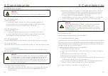
f. Please insert terminal board into terminal block, then will be clamped automatically.
c. Insert the cable through the cap nut for each port. COM2(RS485 IN) COM3(RS485 OUT).
d. Pull down the terminal block on user interface board(See Figure 4.5).
e. Firstly insert cable into terminal board, then tighten the screws (dotted area) with
slotted screwdriver(See Figure 4.5).
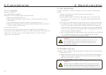
4.2 Ethernet communication
≈
Inverter 1
Inverter 2
Inverter n
Ethernet IN | OUT
Ethernet
Router
Internet
Ethernet IN | OUT
Ethernet IN | OUT
Figure 4.7
Use the RJ45 connectors to perform the Ethernet communication which supports the
Solis Monitoring Platform and Modbus TCP protocol(Both By Default).
NOTE:
When creating daisy chain for Ethernet communication,
all inverters' slave
address must be set to 01.
CAT 5E outdoor rated (cable outer diameter<9mm, internal resistance≤1.5Ω/10m) and
shielded RJ45 connectors are recommended.
The default setting of inverter Ethernet module is DHCP. If a static address is desired, please
refer to the second point below.
Daisy chain is required for multiple inverter communication through ethernet as shown below.
Address: 01
Address: 01
Address: 01
NOTE:
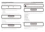
Laptop is required for onsite Ethernet communication commissioning.
If the router doesn't support automatic IP address, use an Ethernet cable
to connect the Ethernet module and your laptop.
Change the Laptop's IP address as 10.10.100.253 and then use a web
browser to navigate to 10.10.100.254.
Connection
of
Terminal
board.
a. Strip the insulation and shield to a suitable length. Use diagram below as a guide.
(in Figure 4.5).
b.
Remove the cap nut from the waterproof cable glands labeled at the bottom of the inverter.
Remove the plug from the fitting. (in Figure 4.6).
8mm
30mm
Figure 4.5
Figure 4.6
Figure 4.8
System
Work
mode
Network
Manual
Restart
Reset
Upgrade
Device information
Type
SN
Firmware version
Current tiom (Time zone)
Embedded Ethernet
1909583738
ME-121001-V1.0.6(20200612800)
Fri Nov 06 2020 16:14:31 GMT+0800
Working time
116 Second
0
Error
NOTE: Laptop IP Configuration
The laptop must be manually configured to set internal IP address to
one in scope of the LAN module in the inverter.
The process will vary depending on your operating system.
Consult the documentation for your operating system to configure a static
IP address for the laptop. Suggested IP address is 10.10.100.253.
Figure 4.9
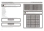
1. Monitoring Platform Solis monitoring only(DHCP)
Connect in daisy chain configuration see Figure 4.7. Use the SN/QR code on the board to
register the system on Solis monitoring website or APP. See APP for details.


