5 Electrical Connection
24 /41
≤
350mm
L1
L2
L3
N
PE
L1
L2
N
L3
≤
350mm
≤
350mm
L1
L2
L3
FIG 5-17
Strip the protection layer and insulation layer
Step 6: If wiring of tracking system power cable is required, refer to" 5.6 Tracker System Power Supply Connection
(Optional)" . Otherwise, skip performing this step.
Step 7: Make the cable and crimp terminal.
W
A
D
W
≤
46mm
12.5
≤
D
≤
16.5mm
A
≤
22mm
For L1/L2/L3/N
W
≤
35mm
10.5
≤
D
≤
16.5mm
For PE(INTERIOR)
L1
L2=L1+3mm
L3=2L1
FIG 5-18
Make the cable
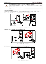
Step 8: Secure the wires to corresponding terminals.
Step 9: Gently pull the cable backwards to ensure firm connection, and fasten the swivel nut clockwise.
20-30
N.m
M12
For L1/L2/L3/N and internal PE cable.
L1
L2
L3
N
L1
L2
L3
L1
L2
L3
N
Gland for internal ground
cable
For cable gland
9-10
N.m
M72
Seal ring-5
For cable
OD=50-57mm
Gland for AC output cable
Press nut
End blocker
Seal ring-4
For cable
OD=43-50mm
Seal ring-3
For cable
OD=36-43mm
Seal ring-2
For cable
OD=30-36mm
Seal ring-1
For cable
OD=26-30mm
End blocker
Press nut
Seal ring-2
For cable
OD=18-25mm
Seal ring-1
For cable
OD=12-18mm
Recommend
FIG 5-19
Recommended AC cable connection position


