3. Installation
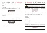
4).
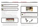
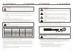
Remove the nuts on the AC terminal block
.
5).
Use a maximum torque 3Nm to fasten the nuts
.
6)
.
Connect the equipment grounding conductor to the ground bar
.
7)
.
Depending on the grid configuration, connect the optional neutral
.
8)
.
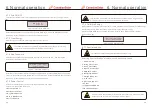
Connect the conductors with crimp terminals to the AC terminals labeled L1, L2 and L3.
A
neutral
is
not
required
for
inverter
operation
.
(see Figure 3.14).
Figure 3.14
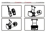
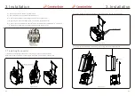
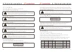
1). Remove the waterproof connector cover and put it in the space as shown.
Retain the four M4 screws by screwing into the screw holes on the mounting rack.
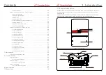
3. Installation
3.7 Installing the inverter
Waterproof cover
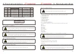
2). Loosen the M6 screws on both sides of the wire box. Do not remove the screws.
Hex screx M6
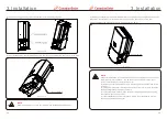
3). Lift the inverter power train, and hang it on the top of the mounting bracket.
Step 1
Step 2
Figure 3.15
Figure 3.16
Figure 3.17
.27.
.26.

