background image

1. Introduction

1. Introduction

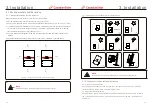
1.2  Unpacking and storage

.7.

.6.

Inverter wire box packing list

CSI


SERIES


GRID

-

TIED


PV


Inverter

CSI

-

50KTL

-

GS

-

FLB

 & 

CSI

-

50KTL

-

GS

-

B

CSI

-

60KTL

-

GS

-

B

 & 

CSI

-

66KTL

-

GS

-

B

INSTALLATION


AND


OPERATION


MANUAL

VERSION


1

.

0

Part #

2-1

 Description

Inverter wire box

2-2

Wire box mounting plate

2-3

Power Train mounting plate

2-4

2-5

 Number

1

1

1

1

Wire box package accessories

1

Installation instructions

Inverter power train packing list


1-1

1-2

2-5

2-1

2-2

2-3

Part #

1-1

1-2

 Description

Inverter Power Train

Power Train packaging accessories

 Number

1

4

Hexagon bolt M6*4

 Remarks

2-4

2-4-1

Hexagon bolt M10*40

2-4-2

Flat Washer M10

2-4-3

Hexagon nut

2-4-4

2-4-5

2-4-6

6

6

6

8

2

Hexagon flange nut

2

Lock plate

Hexagon bolt M6*12

The inverter and wire box ship in separate cartons. When unpacking, please verify all the 

parts listed below are included:

1-3

1-4

1-3

1-4

Handle M10

2

Installation instructions

1

CSI


SERIES


GRID

-

TIED


PV


Inverter

CSI

-

50KTL

-

GS

-

FLB

 & 

CSI

-

50KTL

-

GS

-

B

CSI

-

60KTL

-

GS

-

B

 & 

CSI

-

66KTL

-

GS

-

B

INSTALLATION


AND


OPERATION


MANUAL

VERSION


1

.

0
Summary of Contents for CSI SERIES

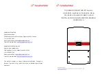
Page 1: ...7 1881 Sales Inquiries Email sales ca canadiansolar com Technical Inquiries Email service ca canadiansolar com CANADIAN SOLAR USA INC North America Headquarters 3000 Oak Road Ste 400 Walnut Creek CA 94596 Tel 1 888 998 7739 Sales Inquiries Email sales us canadiansolar com Technical Inquiries Email service ca canadiansolar com CSI SERIES GRID TIED PV Inverter CSI 50KTL GS FLB CSI 50KTL GS B CSI 60K...

Page 2: ...equipment has supplied The customer is fully liable for any modifications made to the system therefore any hardware or software modification manipulation or alteration not expressly approved by the manufacturer shall result in the immediate cancellation of the warranty Given the countless possible system configurations and installation environments it is essential to verify adherence to the follow...

Page 3: ...rminals 3 5 4 1 Using fuse terminal 23 23 3 6 Making connections to the AC side of the inverter 24 3 6 1 Connecting the inverter to the utility grid 24 3 6 2 Wiring procedure 25 3 7 Installing the inverter 26 4 Communication Monitoring 4 1 RS485 4 1 1 Wiring a single inverter and daisy chain inverter 4 1 2 Maximum allowable inverters using RS485 4 1 3 120 ohm Ω resistor placement 5 Commissioning 5...

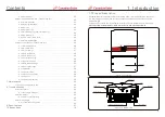
Page 4: ...3 63 63 63 63 63 63 67 70 5 1 Introduction Canadian Solar Three Phase Inverters convert DC power from the photovoltaic PV array into alternating current AC power that can satisfy local loads as well as feed the power distribution grid This manual covers the four 4 Canadian Solar Three Phase Inverter models listed below CSI 50KTL GS FLB CSI 50KTL GS B CSI 60KTL GS B CSI 66KTL GS B Figure 1 1 Front ...

Page 5: ...train packing list 1 1 1 2 2 5 2 1 2 2 2 3 Part 1 1 1 2 Description Inverter Power Train Power Train packaging accessories Number 1 4 Hexagon bolt M6 4 Remarks 2 4 2 4 1 Hexagon bolt M10 40 2 4 2 Flat Washer M10 2 4 3 Hexagon nut 2 4 4 2 4 5 2 4 6 6 6 6 8 2 Hexagon flange nut 2 Lock plate Hexagon bolt M6 12 The inverter and wire box ship in separate cartons When unpacking please verify all the par...

Page 6: ...nstallations must be done in accordance with local and national electrical safety standards 9 8 Use the original box to repackage the inverter seal with adhesive tape with the desiccant inside the box Store the inverter in a clean and dry place free of dust and dirt The storage temperature must be between 16 and 140 F 26 60C and humidity should be between 0 to 100 non condensing Do not stack more ...

Page 7: ...1 10 2 Safety Instructions WARNING To reduce the risk of fire branch circuit over current protective devices OCPD are required for circuits connected to the Inverter CAUTION The PV array solar panels supplies a DC voltage when exposed to light CAUTION Risk of electric shock from energy stored in the inverter s capacitors Do not remove cover until five 5 minutes after disconnecting all sources of s...

Page 8: ...on for the inverter When selecting a location for the inverter consider the following The temperature of the inverter heat sink can reach 167 F 75C The inverter is designed to work in an ambient temperature range between 13 F to 140 F 25 60C If multiple inverters are installed on site a minimum clearance of 20 inches should be kept between each inverter and all other mounted equipment The bottom o...

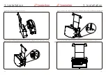
Page 9: ...rter the general properties of the room etc and the quality of the electricity supply the sound level from the inverter can be quite high 3 2 Product handling Please review the instructions below for handling the inverter and wire box 1 The red circles below denote cutouts on the product package Push in the cutouts to form handles for moving the inverter see Figure 3 2 Figure 3 2 Handles used to m...

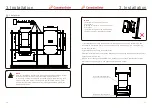
Page 10: ... flat washer 10 nut M10 to attach the inverter bracket on the mounting rack The tightening torque is 24 30 N m 3 3 1 Installation NOTE If it is not installed on the fastened wall the inverter is installed on a steel rack and the steel rack must meet the following requirements a Inverter mounting rack must be in the same plane the mounting rack must not be twisted bent or out of square the flatness...

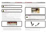
Page 11: ...both side Do not tighten as these will be used later 6 Unscrew the six M5 captive screws on the wire box cover and remove the cover 3 Hang the wire box on the mounting plate 4 Attach the wire box with two M6 screws on both sides and tighten them the torque is 4 6 N m 19 18 ...

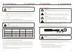
Page 12: ...ity of the PV array output conductors matches the DC and DC terminal labels before connecting these conductors to the terminals inside the inverter wiring box See Section 9 for acceptable wire sizes and Figure 10 1 for screw torque values for the AC and DC connections Both the DC and AC ground wires can be connected to the grounding terminal block see Figure 3 9 Figure 3 9 Grounding terminal block...

Page 13: ...nels in 2 sections WARNING If the amperage per connection is exceeded the inverter could be damaged Ensure all wire sizing procedures are completed per local codes and regulations Ensure the AC grid and DC PV array connections have enough separation to prevent contact with each other 3 5 4 Process of connecting DC wires to terminals 3 5 4 1 Using fuse terminal Figure 3 12 Fuse terminal Loosen the ...

Page 14: ...issible range The exact operating range of the inverter is specified in Section 9 Specifications NOTE Use AL CU transfer bi metallic terminal or anti oxidant grease with aluminum cables and terminals 3 6 2 Wiring procedure 1 Insert the conduit fitting into the opening and tighten the counter nut 2 Attach the conduit to the fitting in the enclosure opening 3 Insert the AC cable through the conduit ...

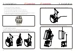
Page 15: ...L3 A neutral is not required for inverter operation see Figure 3 14 Figure 3 14 1 Remove the waterproof connector cover and put it in the space as shown Retain the four M4 screws by screwing into the screw holes on the mounting rack 3 Installation 3 7 Installing the inverter Waterproof cover 2 Loosen the M6 screws on both sides of the wire box Do not remove the screws Hex screx M6 3 Lift the inver...

Page 16: ...tallation it is necessary to ensure the switches on both sides of the wire box are turned OFF The switch knob should point to the OFF 2 There are two ways to install the inverter A Hoisting recommended There are 2 hoisting holes on both sides of the inverter B Lifting There is one M10 holes on each side of the inverter and install the M10 handle please prepare by yourself 3 If using the lifting me...

Page 17: ...igure 3 25 1 Prepare the grounding conductor Crimp a ring or fork M4 size terminal onto the grounding conductor 2 Connect the grounding conductor with crimped terminal to the external ground connection point on the right side of the inverter Use a maximum torque of 20 in lbs 2N m Figure 3 25 Connect the external grounding conductor A B Tee 100 300mm Tee Figure 3 21 Figure 3 22 Figure 3 23 Figure 3...

Page 18: ...unication connection of RJ45 network port When using terminal 5 RJ45 connector to connect use the following wiring sequence Connect the Ethernet cable according to the TIA EIA 568B standard Insert the wire into the RJ45 plug and then use a standard network cable crimping tool to crimp connector to the cable 4 1 RS485 4 1 1 Wiring a single inverter and daisy chain inverters Figure 4 2 Strip the ins...

Page 19: ...se the UP DOWN arrows to highlight ADVANCED SETTINGS Press enter to select 2 The screen will show that a password is required The default password is 0010 press the DOWN key to move cursor press the UP key to change the highlighted digit 3 Use the UP DOWN keys to highlight the SELECT STANDARD option Press enter to select Figure 5 4 4 Select the grid standard for the country of installation YES ENT...

Page 20: ...tring length Low ambient temperatures cause an increase in the string voltage causing potential damage to the inverter 4 Check the polarity of the string All digital meters have a negative indicator that indicates when a voltage is negative in this case a string connected in reverse polarity WARNING Input voltages higher than the maximum value accepted by the inverter see Specifications in Section...

Page 21: ...the inverter will turn on The red DC POWER LED and LCD will be continuously lit 4 Canadian Solar inverters are powered from the DC side When the inverter detects DC power that is within start up and operating ranges the inverter will turn on After turn on the inverter will check internal parameters sense and monitor AC voltage hertz rate and the stability of the supply grid During this period the ...

Page 22: ... Inverter Power Shows instant output power value F_Grid Shows the grid s frequency value Total generated energy value This Month Total energy generated this month Last Month Total energy generated last month Today Total energy generated today Yesterday Total energy generated yesterday Display Duration Description Table 6 1 Information list Inverter SN 00000000000000 10 sec Display series number of...

Page 23: ...n 4 Daily Energy 5 Monthly Energy 6 Yearly Energy 7 Daily Record 8 Communication Data 9 Warning Message The screen can be scrolled manually by pressing the UP DOWN keys Pressing the ENTER key gives access to a sub menu Press the ESC key to return to the Main Menu 6 6 1 Alarm Message The display shows the latest alarm messages see Figure 6 6 Screens can be scrolled 100 manually by pressing the UP D...

Page 24: ...eration 6 6 5 Monthly Energy and Yearly Energy These two options are for viewing the energy generation for selected month or year Figure 6 10 Select month for monthly energy Figure 6 11 Select year for yearly energy YES ENT NO ESC Select 2015 02 YES ENT NO ESC Select 2015 Press DOWN key to move the cursor press UP key to change the digit Press Enter after the month year is selected 2015 02 0510kWh...

Page 25: ...G V1 T 1S Below is the range for each setting for use in the User Def function You may change the limit manually thus creating a custom grid profile by using this function CSI 50KTL GS FL CSI 50KTL GS CSI 60KTL GS CSI 66KTL GS B B B B OV G V1 236 335V OV G V1 T 0 1 9S OV G V2 248 341V OV G V2 T 0 1 1S UN G V1 173 236V UN G V1 T 0 1 9S UN G V2 132 219V UN G V2 T 0 1 1S OV G F1 60 2 63Hz OV G F1 T 0...

Page 26: ...y Press the UP DOWN keys to change the value Enter to save ESC to cancel changes see Figure 6 20 6 7 6 Calibrate Energy Figure 6 20 Calibrate energy YES ENT NO ESC Energy 0000000kWh Selecting Special Settings displays the sub menu shown below 6 7 7 Special settings 1 Grid Filter Set 2 Relay_Protect Set 3 ILeak_Protect Set 4 Ground_Protect Set 5 GRID INTF 02 Set 6 Multiple MPPT Set 7 Voltage MPPT S...

Page 27: ... operation will prevent the inverter from reaching maximum power This function is applicable by maintenance personnel only wrong operation will prevent the inverter from reaching maximum power This function is applicable by maintenance personnel only wrong operation will prevent the inverter from reaching maximum power This function is applicable by maintenance personnel only wrong operation will ...

Page 28: ...m power This function is applicable by maintenance personnel only wrong operation will prevent the inverter from reaching maximum power Figure 6 23 V FRT Set VRT_US STOP FRT_US STOP 6 7 7 11 IgADCheckPRO Set This function is applicable by maintenance personnel only wrong operation will prevent the inverter from reaching maximum power 6 7 7 12 NoSmallPulse Set This function is applicable by mainten...

Page 29: ... excited over excited over excited I II IV III 0 2 6 P Factor Inverter will change power factor when output power changes This mode is not required by UL1741SA This function is applicable by maintenance personnel only wrong operation will prevent the inverter from reaching maximum power 100 of Input Power Vmin Vnom Vstart Vstop Vmax AC Volt 0 Figure 6 28 Volt Watt characteristic 7 VgWatt UL Invert...

Page 30: ...point The default setting is 00 means this function is disabled Figure 6 31 Freq Derate Set Derate Mode 04 OV F Start 60 20Hz 6 7 8 4 10mins Voltage Set This function is disabled and not used for the US 6 7 8 5 Initial Settings In initial settings it will reset each work mode from 6 5 8 1 to 6 5 8 4 back to default This function is applicable by maintenance personnel only wrong operation will prev...

Page 31: ...firmware Press the ENTER key to start the process Press the ESC key to return to the previous menu Figure 6 35 6 7 13 Fan Test Figure 6 37 Selecting Fan Test displays the sub menu shown below This section is applicable to maintenance personnel only Are you sure YES ENT NO ESC Fan Test is a factory test function Press the ENTER key to start the test Press the ESC key to return to the previous menu ...

Page 32: ...The status indicator lights and LCD cover can be cleaned with a soft cloth if they are too dirty to read 7 1 Inverter models with fan assisted cooling The function of the fan is to assist the convection cooling of the inverter If the fan is fails or is not working properly the output power will be curtailed It is important to ensure the fan runs efficiently and replace any damaged fan Replacement ...

Page 33: ... 8 3 1 Troubleshooting guide Canadian Solar inverters are designed in accordance with international grid standards safety standards and electromagnetic compatibility requirements Before delivery to the customer the inverter has been subjected to intensive testing to ensure its optimal operation and reliability In case of failure the screen may display an alarm message stop feeding energy into the ...

Page 34: ...st lower limit with permission from utility Check LCD voltage reading may be a bad measurement circuit Test DC Switch ON Check grid standard Replace inverter Alarms Cause Solution Inverter detects grid Frequency as too high OV G F Over Grid Frequency Test DC switch OFF Check frequency at the inverter test points If Frequency measures high adjust upper limit with permission from utility Check LCD r...

Page 35: ... installation Check cable with string tester Physically check cables Inspect panel junction boxes Inspect cable connections Reset inverter Replace inverter Table 8 1 Fault messages and descriptions 9 Specifications Compliance MPPT operation range Number of MPPT strings per MPPT Rated output power Max output power Rated grid voltage Grid voltage range Operation phase Rated grid output current Outpu...

Page 36: ...cy Max Efficiency Protection Size inch Weight Topology Internal consumption Running temperature Ingress protection Interface Design lifetime Operating Range Utility Frequency Operation Surroundings Humidity 200 850Vdc 60kW 480Vac 422 4 528Vac Three phase 0 8leading 0 8lagging 50mA 60Hz 25 60 RS485 WIFI GPRS Optional 20years 59 5 60 5Hz 4 4 60kW 72 2Aac 1W Night 0 100 Condensing 3 1000Vdc 24 8W 40 ...

Page 37: ...rature All inverters will begin a sloped derate at 45C ending at 50 output power at 60C Temperatures above 60C and below 25C will derate to 0 output power 100 50 0 45 60 T P 25 P V curve for CSI 50KTL GS FLB Power W 50000 17500 200 568 850 990 1000 Voltage V Figure 10 3 CSI 50KTL GS FLB Inverter output power by input voltage P V curve for CSI 50KTL GS B Power W 50000 17500 200 568 850 990 1000 Vol...

Page 38: ... 60000 21000 200 526 850 990 1000 Voltage V Figure 10 5 CSI 60KTL GS B Inverter output power by input voltage P V curve for CSI 66KTL GS B Power W 66000 23100 200 579 850 990 1000 Voltage V Figure 10 6 CSI 66KTL GS B Inverter output power by input voltage ...

Page 39: ...er to the mounting bracket and ensure it is irmly attached Ensure the inverter has proper clearances and are properly ventilated Completed 5 Serial number Record the product serial numbers located on the side label Serial Numbers attached list 6 Solar modules Conirm PV module installation completion Record the total power of the PV modules Completed Record kWp in Notes 7 DC input and AC output con...

Page 40: ...f checking Initially GridV Outlimit and GridF Outlimit will be displayed then the inverter will switch to Standby mode 2 Switch on the AC switch The Grid faults will clear automatically In Standby mode the Power LED is solid green the Run LED is off the Grid LED is solid green and the Fault LED is off Completed Record LEDs status in Notes CSI xx KTL GS 1 Switch the grid supply main Switch AC ON irst...

Page 41: ...lays the information of GENERATING Completed Record LEDs status in Notes 4 Power generation After grid connection record power output of inverter Completed Record power in Notes 5 Date Time setting Set the current date and time using the front panel interface Completed Record current date time in Notes 6 Communication setting if avail Set communication with a unique address for each inverter Compl...

Page 42: ...variances Inverter model Inverter irmware revision DSP LCD Number of inverters Inverter mounting tilt Output power Input DC voltage Insulation limit K PV start up voltage Grid V Max V Min Frequency Max Min Reactive compensation PF Coniguration MPPT Individual MPPT Parallel Monitoring RS485 Ethernet Monitoring equipment and supplier PV module manufacturer PV model DC cable size AC cable size Transf...

Page 43: ...g This checklist is not a replacement for the user manual Please read the user manual prior to inverter site selection and installation 3 PHASE STRING INVERTERS KTL SERIES CSIF ST 016 A 0 INSTALLER S NAME INSTALLER S SIGNATURE COMPANY DATE Inverter serial numbers 1 2 3 4 5 6 7 8 9 10 11 12 13 14 15 16 17 18 19 20 21 22 23 24 25 26 27 28 29 30 31 32 33 34 35 36 37 38 39 40 41 42 ...

Reviews: