13
of 42
Combustex BMS-2000 [5.03] Operations Manual -
2. OPERATION
Phone:
403.342.4494
|
Web:
www.canaltaflow.com
For operational, technical or installation assistance, please contact us.
Call Us Toll Free:
1-855-226-2582
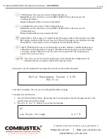
2.5 OUTPUT STATUS PAGE
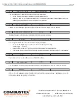
Page three of the BMS-2000 controller displays the status of the following:
• Pilot Solenoid Valve
• Main Solenoid Valve
• Ignition Output
• Purge Blower Output
NOTE:
This page is non-adjustable and is for indication only.
2.6 AUX. ANALOG INPUTS AND SHUTDOWNS
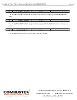
Page four of the BMS-2000 controller displays two monitored values:
• Spare Thermocouple Input #1 (if selected)
• This value can be labeled as ‘ #1 Stack’, ‘Bath’ or ‘Process’
• Input can be used for indication only, or as a HTSD
• When used as a HTSD, this value appears in brackets beside the actual temperature
• Supply Voltage
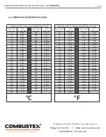
* Note: Displayed temperature units are specified at time of order.
NOTE:
This page is non-adjustable and is for indication only. Shutdown limits, which appear in brackets,
are definable in the configuration menu (see section 3.2).
3. #1 Pilot : Open
#1 Main : Open
#1 Ign. : Off
Purge Blower: Off
4.
#1
Stack
:
+315C
[+700]
Supply Voltage
:
+24V
[+20]


