28
of 42
Combustex BMS-2000 [5.03] Operations Manual -
5. INSTALLATION
Phone:
403.342.4494
|
Web:
www.canaltaflow.com
For operational, technical or installation assistance, please contact us.
Call Us Toll Free:
1-855-226-2582
INSTALLATION
5.1 OVERVIEW
Controller Location
The BMS-2000 is CSA certified for Class 1, Division 2 Groups A, B, C and D hazardous locations. It is also
rated NEMA Type 4x and can be readily installed outdoors. The BMS is ideally located away from the
flame arrestor in an area not subject to extreme heat and vibration. The distance between the BMS unit
and pilot / ignitor assembly can be up to 50 feet at specified interconnecting wiring guages (see below).
Greater distances can be achieved if the wiring gauge is increased and line resistance does not exceed
0.5
Ω
. When installed on the outside wall of a building, care must be taken to protect the controller from
heavy runoff or falling snow and ice. Particular attention must be paid to Class 1, Div. 1 building vents
which limit the location of Div. 2 rated equipment to within 1.5 meters of such openings.
Conduit Entry
The preferred location for conduit entry is the bottom of the BMS-2000 enclosure. Top entry is also
available, but care must be taken to ensure a weather tight seal through the use of a Myers Hub or other
approved CEC wiring methods.
Wiring Methods
1. Use rigid steel or aluminum conduit.
2. Interconnecting wiring:
• Power to the BMS and interconnecting power to the igniter should be (minimum) gauge 14 Belden
or equivalent with shields tied to the BMS end only.
Note:
If the distance between the BMS and pilot
/ ingitor assembly is greater than 50 feet, increase the wire gauge to achieve line resistance no greater
than 0.5Ω.
• All other digital and analog inputs should be (minimum) gauge 16 or equivalent.
3. Interconnecting wiring between thermocouples and the BMS must be type K extension grade
thermocouple wire with a shield. Tie shields to the BMS end only.
4. Ground the negative of the power input to the chassis ground.
Solenoids
The pilot and main solenoids must be rated for the same voltage as supplied to the BMS, and approved
for the area classification where they are being installed. Solenoid valves must be configured in
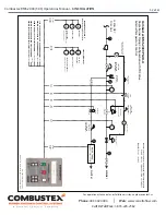
accordance with the instrumentation P&ID drawings contained in this manual (see pp. 31 - 35). All tubing
should be a minimum of 3/8” and properly supported using raceway or tubing clips.
Power Supply Requirements
The BMS-2000 requires a 10 - 30 volt DC supply free of spikes and interference. The power source
should be rated for at least 3 Amperes for a typical system. This requirement will be higher if additional
solenoids or other loads are driven from the BMS outputs.

