30
of 42
Combustex BMS-2000 [5.03] Operations Manual -
5. INSTALLATION
Phone:
403.342.4494
|
Web:
www.canaltaflow.com
For operational, technical or installation assistance, please contact us.
Call Us Toll Free:
1-855-226-2582
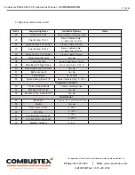
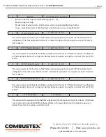
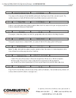
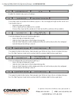
5.5 DIGITAL OUTPUT CONNECTIONS
Sixteen digital outputs are available:
1. Igniter #1
2. Igniter #2
3. Status #1
4. Status #2
5. Pilot #1
6. Pilot #2
7. Main #1 SD Valve
8. Main #2 SD Valve
9. Main #1 ON/OFF Control
10. Main #2 ON/OFF Control
11. Purge Blower
12. Spare #1 (not utilized in this software version)
13. Spare #2 (not utilized in this software version)
14. Spare #3 - SD indication (ON when there are no shutdowns active; OFF when there are any
shutdowns active)
15. Pilot #1 Unlatch (available upon request - for latching solenoids only)
16. Pilot #2 Unlatch (available upon request - for latching solenoids only)
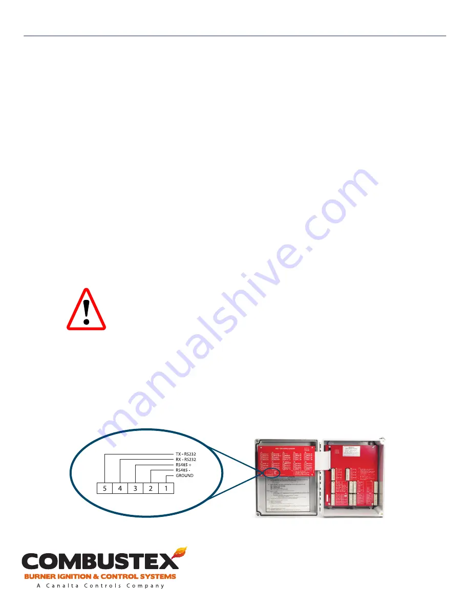
5.6 MODBUS CONNECTIONS
Five Modbus terminals are located on the front circuit board of the Combustex BMS controller: two
terminals for Modbus RS232, two terminals for Modbus RS485, and one for ground. Ensure power to the
BMS controller is off before terminating wires. A Modbus Map is available by contacting Combustex
directly.
Note:
These outputs are powered directly from the BMS controller.
Any
attempt to power externally will damage the controller.
All outputs will
be at the same potential as the supplied power to the BMS.


