37
of 42
Combustex BMS-2000 [5.03] Operations Manual -
6. TROUBLESHOOTING
Phone:
403.342.4494
|
Web:
www.canaltaflow.com
For operational, technical or installation assistance, please contact us.
Call Us Toll Free:
1-855-226-2582
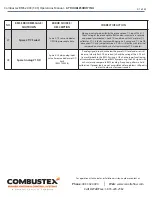
NO.
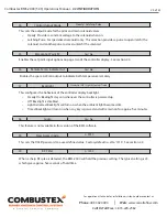
BMS ERROR MESSAGE /
SHUTDOWN
ERROR SOURCE /
DESCRIPTION
CORRECTIVE ACTION
1
Auxiliary Bath High Temp
Bath Aux. Contact sensor
indicating high temperature of
vessel.
(BMS TS2 #3-4)
If S/D is activated and there is no indication by other sensors that alarm
level was crossed, check wiring of DI Bath HTSD. If wiring is OK, check
bath temperature sensor’s contact switch. Replace if switch is faulty.
Otherwise, wait for Bath Temperature to fall below preset alarm level and
shutdown should be satisfied. If problem persists, perform
DI Test 01
.
2
Bath High Temp.
Bath T/C probe indicating
High Temperature Alarm. Bath
temp from T/C at TS5 #7-8 has
exceeded the HTSD value.
If bath temperature (indicated by a reference gauge) falls below
preset HTSD value (set in CONFIG menu) and S/D cannot be cleared,
check wiring and condition of Bath T/C with a mV or T/C calibrator. If
T/C is faulty, replace with new one. If T/C and wiring is OK, perform a
field calibration to Bath T/C input. If proper tools are not accessible or
problems persist, contact Combustex for repair request.
TROUBLESHOOTING SHUTDOWN CONDITIONS
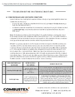
6.1 ERROR MESSAGES AND SHUTDOWN CONDITIONS
System function errors resulting from equipment failure or faulty wiring (including BMS hardware) are
indicated in one of two ways:
• An error message is displayed on the BMS 2000 LCD screen (e.g.
Flame #1 T/C Failed
indicating a
faulty thermocouple on pilot #1).
• A shutdown cannot be cleared from the annunciation screen despite having it’s condition satisfied
(e.g.
Bath High Temp.
cannot be cleared when actual bath temperature falls below the preset
HTSD value).
Note:
All shutdowns are factory set to YES by default. If a specific shutdown is not required, it must
be manually set to NO in the Configuration Menu (see Section 3 pp. 15 - 24). If a specific shutdown is
configured to YES but no field device device is terminated to its slot at the BMS controller, a shutdown
message will be displayed and the controller will NOT be permitted to START.
DI Test 01
is a generic procedure to test the function of all discrete inputs on the BMS controller, and
should be used if the recommended corrective actions described below fail to remedy the problem.
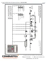
To perform the test, disconnect both wires from the DI terminal (refer to the BMS 2000 wiring diagram
p. 31). If the specific shutdown is enabled in the configuration menu, the DI will be activated. Use a
wire to jumper the +/- terminal of the DI.
Note:
Power down the controller when removing wires and
installing jumper wire.
With acknowledgement, the S/D should automatically clear from the shutdown
list on display Page 1. The test result is classified as
positive
if the DI functions as above. If the DI fails to
perform as above, the test result is classified as
negative
and may indicate a hardware malfunction on
the BMS controller. Contact Combustex for assistance, service or warranty.

