background image

XB, HV, HVA, HVAR, ADD, ADDR, DDS, DDP, SXB, SADD  

M0112_NOV 2020

Page 5 of 8

www.CANARM.COM

Canarm Ltd. - Corporate Head Office    

2157 Parkedale Avenue, PO Box 367    Brockville, Ontario   Canada   K6V 5V6 

Tel: (613) 342-5424              Fax: (613) 342-8437               

hvacsales@canarm.ca                      

www

.canarm.com 

Canarm Ltd. uses pillow block bearings. 
 
•     Before removing the bearings mark the positions of the fan blade, bearings and pulley on the shaft. 
•     Note the clearance between the fan blade and the venturi. 
•     Remove the pulley and fan blade from the shaft using a puller. 
•     Unbolt the bearings and remove the shaft and pillow blocks as one unit. 
•     Clean the shaft and remove any marks using a file or emery cloth then remove the bearings using a bearing 

      puller. 

•     Inspect the shaft and replace if necessary. 
•     Mount the new bearings on a section of the shaft that is not worn by tapping the inner ring face using a soft 

      mallet. 

•     Align the setscrews on the bearings and then tighten one setscrew on each bearing. 
•     Loosely install the bearings on the bearing mount. 
•     Rotate the shaft to find the center of free movement. 
•     Install the propeller adjusting the bearing location to center the blade in the venturi. 
•     Tighten the bearing bolts to the proper torque rating  
•     Turn the propeller by hand the propeller should rotate freely with the same resistance as before the bearing 

       bolts were tightened. 

•     Tighten all setscrews to the proper torque rating 
•     Install pulley and adjust belt tension. 
 
You should go through the start up steps as outlined above. 
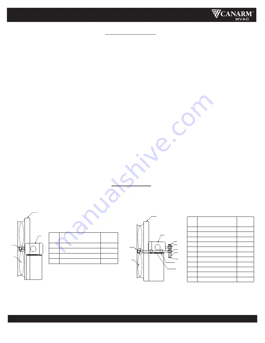
REPLACEMENT

PARTS LIST

MODELS: DDS, DDP, ADD, ADDR                                                        

MODELS: XB, HV, HVA, HVAR  

4

3

2

1

MOTOR

1

WELDED FAN ASSEMBLY

PROPELLER BUSHING

FAN ASSEMBLY

PROPELLER

DESCRIPTION

QUANTITY

1

1

1

1

3

2

ITEM

4

DRIVEN SHEAVE BUSHING

MOTOR SHEAVE BUSHING

FAN ASSEMBLY

PILLOW BLOCK BEARINGS

3

DRIVEN SHEAVE

“V” BELTS

FAN SHAFT

PROPELLER

PROPELLER BUSHING

9

11

10

6

8

7

5

4

DESCRIPTION

MOTOR SHEAVE

ITEM

2

1

1

2

2

1

1

1

1

1

1

QUANTITY

1

1

WELDED FAN ASSEMBLY

MOTOR

4

11

9

10

6

8

7

5

2

3

1

Summary of Contents for ADD

Page 1: ...nted to a wall require a different wall opening than fans mounted in cabinets or sleeves For specific dimensions refer to the submittal drawing for the specific fan configuration 2 Mount the fan in the opening with the fan panel directly over the load bearing support and if this is not practical angle supports must be provided to transfer the fan weight to the load bearing structure 3 Caution The ...

Page 2: ...event it from entering the shaft and propeller area 5 Disconnect switches are recommended and should be located near the fan in order to swiftly cut off power in case of an emergency and maintain complete control of the power source 6 Some motors may have to be removed in order to make the connections in the motor terminal box 7 Follow the wiring diagrams on the motor nameplate 1 Wall Fans Extend ...

Page 3: ...t the same time check the sheaves for chips dents or rough surfaces that could damage the belt The correct belt tension is important Too tight a belt will result in excess bearing pressure which can cause premature bearing failure and may cause the motor to overload too loose a belt will result in slippage which will burn out belts Proper belt deflection should be 1 64 half way between sheave cent...

Page 4: ... pulley Loosen the setscrews on the pulleys and remove from either the motor or fan shaft using a two or three jaw puller Remove any shaft imperfection such as setscrew mark using a file or emery cloth Install the replacement pulleys tightening all setscrews to the recommended torque rating see chart and ensuring that they are properly aligned Pulley alignment is achieved by moving the pulleys on ...

Page 5: ... the setscrews on the bearings and then tighten one setscrew on each bearing Loosely install the bearings on the bearing mount Rotate the shaft to find the center of free movement Install the propeller adjusting the bearing location to center the blade in the venturi Tighten the bearing bolts to the proper torque rating Turn the propeller by hand the propeller should rotate freely with the same re...

Page 6: ...ves Improper fan installation Static pressure higher than design MOTOR OVERLOADING Impeller rotating in the wrong direction Improper fan speed Defective motor Fan speed higher than design Filters missing TOO MUCH AIR Static pressure lower than design Fan speed higher than design Lack of electricity to the fan Fan wired improperly Broken or missing belt FAN DOES NOT OPERATE Missing or blown fuses O...

Page 7: ...excess of 50 pounds should also be supported using hanging rods or by supports placed underneath the fan Wall supply fan with cabinet back guard motorized shutter and weather hood The drawing below illustrates the typical installation of a supply fan with a cabinet back guard motorized shutter with end switch and weather hood in a masonry wall The installer shall provide angle iron framing and sui...

Page 8: ... defects in materials and workmanship to the extent that within a period of one year from the date of purchase CANARM Ltd shall either repair or replace at CANARM s option and unit or part thereof returned freight prepaid and found to be defective This warranty does not include any labour or transportation cost incidental to the removal and reinstallation of the unit at the user s premises Compone...

Page 9: ...e différente de ceux installés dans un armoire ou manchon Pour les dimensions spécifiques reportez vous au dessin de soumission pour la configuration spécifique du ventilateur 2 Montez le ventilateur dans l ouverture avec le panneau du ventilateur directement sur le support porteur et si cela n est pas pratique des supports d angle doivent être fournis pour transférer le poids du ventilateur sur l...

Page 10: ...r dans la zone de l arbre et de l hélic 5 Des sectionneurs sont recommandés et doivent être localisés près du ventilateur afin de couper rapidement l alimentation en cas d urgence et maintenir un contrôle complet sur la source d alimentation 6 Certains moteurs peuvent être retirés pour effectuer les connections électriques dans la boîte du moteur 7 Suivez le diagram de connection sur la plaque sig...

Page 11: ... est importante Une courroie trop serrée peut causer une pression excessive sur les roulements ce qui peut causer une défaillance prématurée des roulements et entraîner une surcharge du moteur Une courroie trop détendue entraînera un glissement qui brûlera les courroies La déflexion appropriée de la courroie doit être de 1 64 po à mi chemin entre les centres des poulies pour chaque pouce de portée...

Page 12: ...t un extracteur d engrenage à deux ou trois mâchoires Retirez tout imperfection à l arbre tel que marque de vis en utilisant une lime ou d une toile émeri Installez les poulies de rechange en serrant toutes les vis de réglage au couple nominal recommandé voir tableau et s assurer qu elles sont correctement alignées L alignement des poulies se fait en retirant les poulies de leur arbre respectif ou...

Page 13: ...age sur les roulements puis serrez une vis de réglage sur chaque roulement Installez les roulements sans serrer sur le support de roulement Faites tourner l arbre pour trouver le centre du mouvement libre Installer l hélice en ajustant l emplacement du roulement pour centrer la pale dans le venturi Serrez les boulons de roulement au couple nominal approprié Tourner l hélice à la main l hélice doit...

Page 14: ...ncue SURCHARGE DU MOTEUR Rotation de la turbine dans la mauvaise direction Vitesse incorrecte du ventilateur Moteur défectueux Vitesse du ventilateur plus élevée qu il est conçu Filtres manquants TROP DE VENTILATION Pression statique plus basse que celle concue Vitesse du ventilateur plus élevée qu il est conçu Perte de courant électrique au ventilateur Branchement électrique incorrect Courroie ma...

Page 15: ...ction arrière volet motorisé et hotte étanche Le dessin ci dessous illustre l installation typique d un ventilateur d alimentation avec un cabinet une protection arrière un volet motorisé avec interrupteur d extrémité et une hotte contre les intempéries dans un mur de maçonnerie L installateur doit fournir un cadrage avec cornière et des fixations appropriées boulons hexagonaux ou vis tire fond po...

Page 16: ... s appliquent GARANTIE CANARM Ltd garantit que chaque nouveau ventilateur est exempt de défauts de matériaux et de fabrication dans la mesure où dans un délai d un an à compter de la date d achat CANARM Ltd réparera ou remplacera au choix de CANARM toute unité ou partie de celle ci fret retourné prépayé et jugé défectueux Cette garantie ne comprend pas les frais de main d œuvre ou de transport lié...

Reviews: