


C
I
RCU
L
AR
DUCT
FIGURE 5
Q
U
I
CK
CO
NN
ECT
H
OUSE
WI
RES
PRODUCT
WI
RES
FIGURE 6
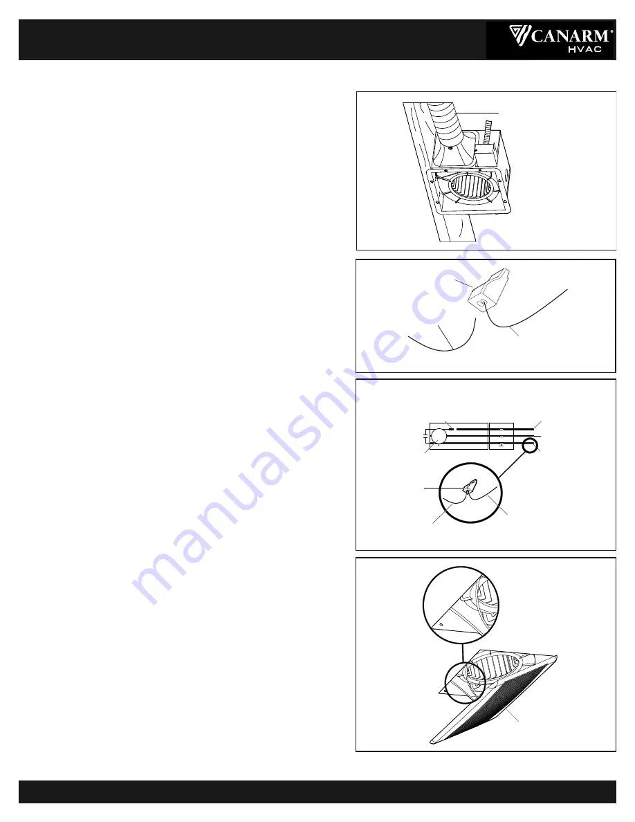
5.
DUCT CONNECTION (FIGURE 5)
a) Install a circular duct to the outlet and secure it With duct tape or
clamps to the outlet.
b)
Install the duct with a gradient of 1˚ ~ 2˚ to the outside.
6.
USING QUICK CONNECT (FIGURE 6)
WARNING: Wiring must comply with all applicable electrical codes.
Turn power OFF before removing or installing connectors.
WARNING: COPPER to COPPER ONLY. Do not use on Aluminum
wire.
CAUTION: The Quick Connect accessory part should be installed
as per instructions below.
NOTE: Connector is reusable on solid wires of the same wire
gage or smaller. Do not reuse connector on stranded wires.
a) Strip the wires so half of the bare wire is showing.
b)
Grip the wire firmly and push the stripped end of the wire into the
open port of connector). Use only one stripped end of the wire per
port.
c)
Verify the stripped end of the wire is fully inserted to the back of the
connector.
NOTE: Important wire information. Maximum temperature rating 105°C (221°F).
600 volts maximum for building wire and 1000 volts maximum in signs and
lighting fixtures. Flammability rating of the wires must meet UL94-V2. The
acceptable wire range includes: Solid: 12-20 AWG, Stranded: 12-16 AWG (≤19
STRAND); 18AWG (7 STRAND), Tin bonded: 14-18 AWG (≤19 STRAND).
7.
CONNECTING WIRING FROM UNIT TO HOUSE
(FIGURE 7)
WARNING: Make sure that the main power is off.
WARNING: COPPER to COPPER ONLY.
Do not use on Aluminum wire.
CAUTION: The Quick Connect accessory part should be installed
as per instructions below.
a) Connect house wires to ventilation fan wires.
b) Match colors as shown (black to black, white to white, and green
to green) using quick connects or wire nuts (not provided).
c) Replace the junction box cover. Do not pinch the lead wires.
8.
MOUNTING THE GRILL (FIGURE 8)
a) Use the spring clips to pinch mount and insert the grill into the
narrow rectangular slots inside of the fan housing next to the fan
motor.
HVAC PRODUC S
HVAC PRODUC S
HVAC PRODUC S
BPT18-34A-1 & BPT18-54A-1
BATHROOM EXHAUST FANS
BPT18-34A-1-M & BPT18-54A-1-M-05_05_15
Page 3 of 4
INSTALLATION INSTRUCTIONS
CONTINUED...
PRODUC
T
W
I
RES
H
OUSE
W
I
RES
QU
I
CK
CO
NN
EC
T
A
U
T
O
MATI
C
T
ER
MINAL
C
A
P
A
C
IT
OR
J
U
N
C
TI
O
N B
O
X
M
O
T
OR
(black) to switch
(white) to neutral
(green) to ground
FIGURE 7
GR
ILL
FIGURE 8


