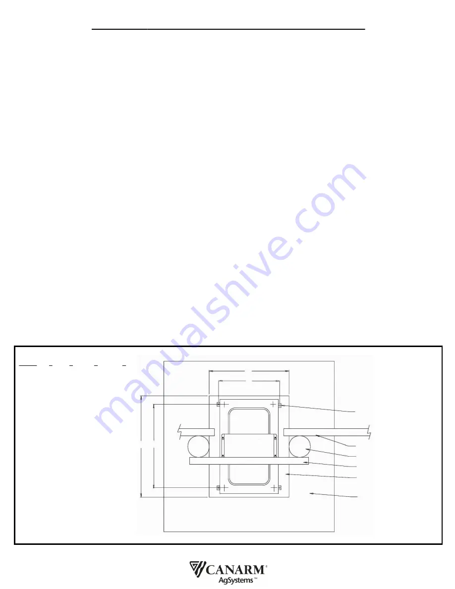
A
C
B
D
HOLD-DOWN BRACKETS
ONE IN EACH CORNER
(PRE-INSTALLED IN WATERER ON LW50)
FENCE RAIL
FENCE POST
REMOVABLE RAILS ABOVE WATERER
RAISED CONCRETE PAD 3" THICK
6’ X 6’ X 6" THICK BASE
DIAGRAM 1
-
LOCATING AND MOUNTING THE WATERER
(
TOP VIEW OF WATERER INSTALLED ON FENCE LINE)
READ AND SAVE THESE INSTRUCTIONS
MODELS: HL50-09, H50-09, H100-09, H200, P25, P50 and P100
General Information:
Canarm’s Energy Efficient Heated Livestock Waterers are designed for both durability and ease of use. Our H50/HL50/H100/H200/HLW-P50 models have
a strong, double wall design, with 2” or more of injected polyurethane foam insulation, providing a minimum of an R15 insulation value, one of the highest
in the industry.
The hinged bowl is designed to lift up for easy cleaning, as well as quick access to all internal components. Stainless steel bowl construction ensures long
life, and eliminates the risk of chipping paint and rust contamination.
Canarm heated livestock waterers come with a 190 watt (P25), a 300 watt (HL50/H50/P50), 500 watt (H100/P100) or a 800 watt (H200 unit has 1 - 320
watt + 1 - 500 watt) thermostatically controlled heating element. An external pilot light (not available on P25, P50 or P100) turns on when the thermostat
setting is reached - but it is not directly indicating the heating element has turned on. The thermostat is adjustable and can be accessed though the control
cover.
The non-siphoning design and nylon control valve and float are designed for trouble free operation in all seasons.
IMPORTANT SAFETY INSTRUCTIONS
When using the electrical equipment, basic safety precautions should always be followed, including the following:
(a)
READ AND FOLLOW ALL INSTURUCTIONS
(b) A green terminal (or a wire connector marked “G”, “GR”, “GROUND” or “GROUNDING”) is provided within the control box. To reduce the risk of electric
shock, connect this terminal or connector to the grounding terminal of the electric service or supply panel with a continuous copper wire in accordance
with the Canadian Electrical code, Part 1.
(c) This product shall be protected by a Class A ground fault circuit interrupter.
(d)
SAVE THESE INSTRUCTIONS
.
INSTALLATION
ATTENTION: Electrical installation and maintenance MUST be performed by a qualified technician!
Locating the Waterer: (DIAGRAM 1.)
The waterer can be located indoors or out, and can be positioned on the fence line to supply water to two pens or positioned centrally in the pen to water
larger numbers of animals. When locating the waterer on a fence line the rails above the waterer should be removable to permit the unique easy cleaning
feature to operate. The waterer is equipped with a hinged bowl for easy cleaning, just swing the bowl up to dump the dirty water. This also provides quick
access and more space for installation and maintenance procedures.
Mounting the Waterer:
The waterer should be mounted on a 6' x 6'x 6" thick concrete base with a 3" thick raised concrete pad. Bolts can be positioned in the concrete or drilling
and concrete anchors can be used after the concrete has cured. Place the waterer in position and secure with the brackets provided. The brackets bolt
to the side of the waterer in the weld nuts located near each corner.
(
NOTE:
Poly models have molded corners on the inside of the housing. Drill concrete anchors through the pilot holes provided).
Automatic Heated Livestock Waterers
Instruction Manual
M0003 - 03/18 Page 2 of 5
A
B
C
D
MODEL A
B
C
D
HL50
24” 30” 18-1/8”
25”
H50
24” 30” 18-1/8”
25”
H100
24” 30” 23-3/8” 29-1/4”
H200
24” 30” 25-1/8” 39-7/8”
HLW-P25
24” 24”
INTERNAL
INTERNAL
HLW-P50
24” 30”
INTERNAL
INTERNAL
HLW-P100
28” 36”
INTERNAL
INTERNAL
REMOVABLE
VALVE COVER


