Appendix B ‒ Vibrating Wire Measurement Configuration
MLTDR-W-50S User's Guide
63
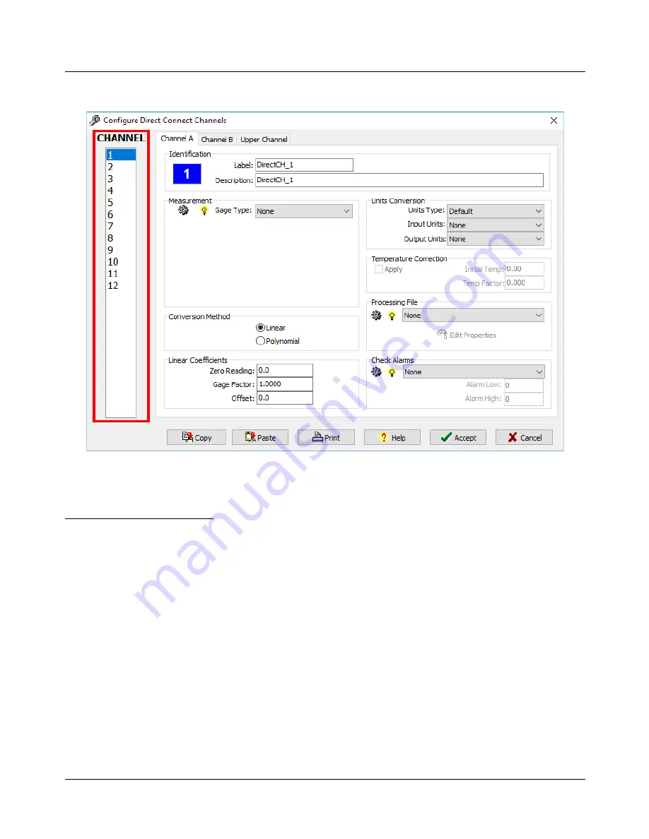
Initially, the form displays options for the first Channel. Note the
CHANNEL
selector on the left of the form,
from which the Channel being configured can be selected.
(The default Channel Configuration form with CHANNEL selector highlighted)
See the Section 3.4 of the
MultiLogger User's Guide
for more detail on all the form options. This guide
provides example typical configurations.
The key settings are as follows:
▪
Label
: The unique identifier for the instrument connected.
▪
Description
: The description for the instrument connected. Often location or instrument serial numbers are
used in the Description field.
▪
Measurements
: Configures the measurement to be made. For a gage connected to the CR6,
Vibrating
Wire
must be selected as the
Gage type
.
▪
Conversion Method
: How to convert the measurement to engineering units.
▪
Linear or Polynomial Coefficients
: Supplied by the instrument manufacturer.
▪
Units Conversion
: Configure the conversion to alternate output units.
▪
Upper Channel Label
: The unique identifier for the instrument temperature measurement.
▪
Upper Channel Device
: Configures the temperature measurement to be made.
▪
Upper Channel Units
: Configures the units of the temperature measurement.


