Section 1 ‒ Introduction
8
MLTDR-W-50S User's Guide
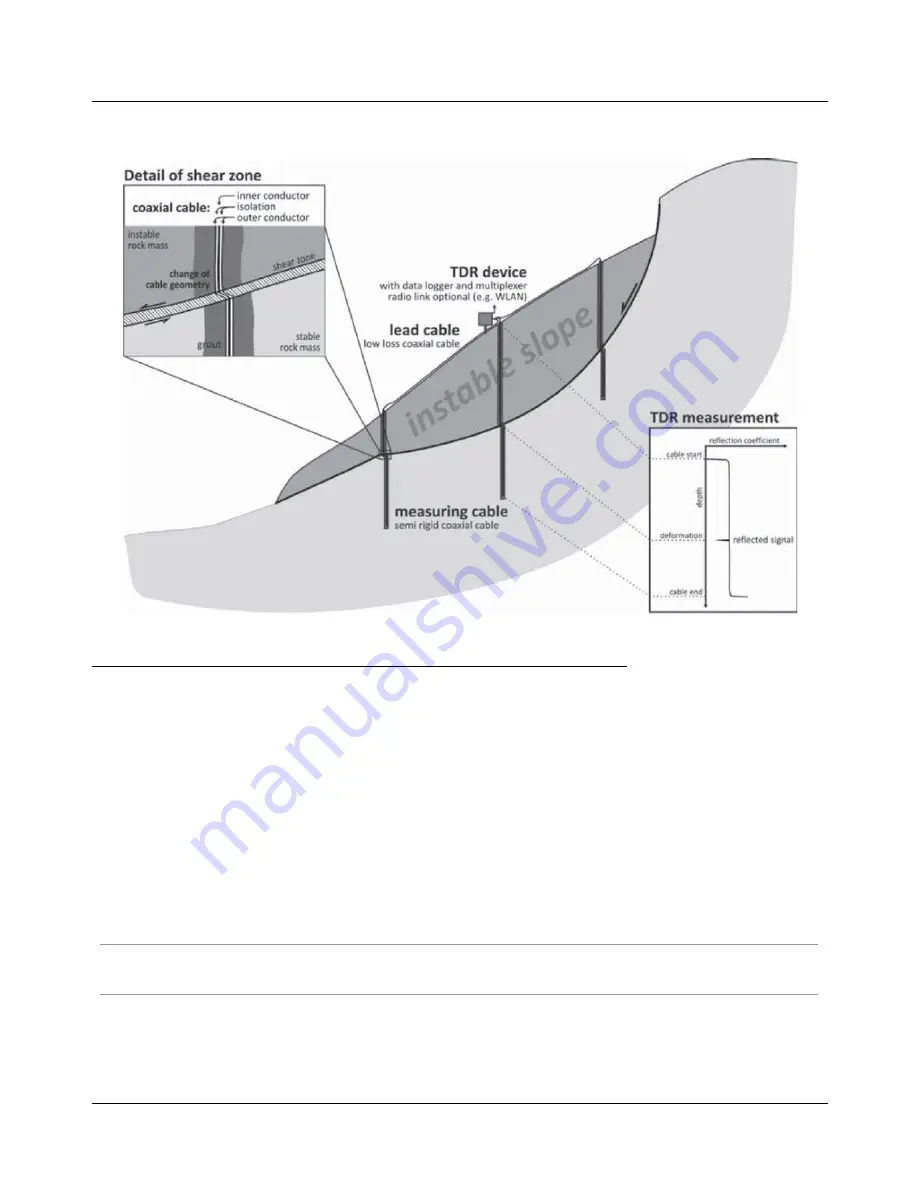
Multiple cables may be embedded in an unstable slope to allow accurate profiling of the depth and progression
of a failure mode, as shown in the following illustration.
(TDR cables embedded on a slope - Illustration courtesy Singer 2006)
Typical cable abnormalities/failures and resultant change in reflection coefficient:
•
An open cable end (∞ impedance) will return a maximum reflection coefficient, typically a value close
to 1.
•
A shorted cable end (0 impedance) will return a minimum reflection coefficient, typically a value close
to -1.
•
Cable abrasion causing abnormalities in the outer conductor, including holes or breaks, will typically
result in a positive spike in the coefficient.
•
Crimping of the cable, usually the result of deformation or pre-applied during installation, will increase
capacitance causing a negative spike in the coefficient.
•
Corroded cable connections, often due to splicing, will typically cause a reduction in the impedance
and hence a negative spike in the coefficient. If the damage is severe enough, no further reflections
past the location will be received, essentially ending monitoring of the cable beyond that location.
•
Dielectric property changes due to water ingress will typically cause a positive spike in the coefficient.
Note - TDR monitoring does not provide absolute movement data, the reflection coefficient is simply a relative
measure of the signal reflection. However, continued observation of reflections can provide indication of continued
deformation or a stabilization of the failure.


