background image

23  

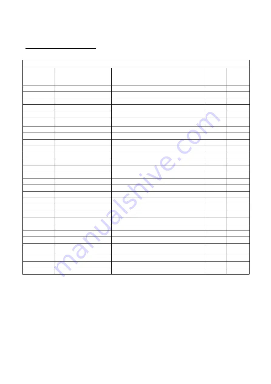
Power Head Parts List 

785HE POWER HEAD (DOWNFLOW) 

Replacement 

Part Number  MFG Part Number 

Part   Description 

DWG #  Quantity 


60010574 

Screw-ST3.5X13 

B01 

10 


60010673 

Screw-ST2.9X10 

B02 


Screw-ST3.5X25 

B03 


BNT85HE Piston Rod Guide Plate 

B04 


60010050 

Motor-12v/2rpm 

B05 


97000967 

Motor Power Cable 


60010660 

Motor Pin 

B06 


60010573 

BNT85HE Mounting Plate 

B07 


92389 

BNT85 Drive Gear 

B08 


60010099 

Screw-ST2.9X13(Large Washer) 

A24 


60010100 

Washer-3x13 

B09 


60095078 

BNT85 Main Gear 

B10 


60095093 

BNT185 Housing 

B11 


92392 

BNT85HE Brine Gear(Downflow) 

B12 


60010672 

Magnet(3×2.7) 

B13 


Washer-4x12 

B14 


60010661 

Screw-ST4.2X12(Large Washer) 

B15 


60095082 

BNT85HE Piston Rod 

A04 


60095622 

Screw-ST3.5X16 

B16 


60010179 

BNT85HE Rear Main Pcb(Downflow) 

B17 


60010115 

CABLE METER 


Meter Strain Rlief 


60010124 

Power Cable 


Power Strain Rlief 


60095099 

Wire Rope-3×100 


60010180-1.7A 

BNT85HE Display (Downflow) 

B18 


60010240 

BNT85 Wiring Harness 


60095081 

BNT85 Cover 

B19 

Summary of Contents for 785 HIMTLC PLUS Series

Page 1: ...fied lubri cant to all seals 3 This system is not intended for trea ng water that is microbiologically unsafe or of unknown quality without adequate disinfec on before or a er the system 4 Backwash f...

Page 2: ...water that is microbiologi cally unsafe or of unknown quality without adequate disinfection before or after the system For your safety the information in this manual must be followed to minimize the...

Page 3: ...ly lead free solder and flux for all sweat solder connections as required by state and federal codes Maximum allowable inlet water pressure is 125 psi If daytime pressure is over 80 psi night time pre...

Page 4: ...Exchange Media ft3 1 32ft3 1 76 ft3 2 20 ft3 2 64 ft3 Tank Size 10x54 12x52 13x54 14x65 Top Cone Yes Yes Yes Yes Tank Jacket Media Loaded Yes No No No Brine Tank Inches 20 3 x 37 4 20 3 x 37 4 20 3 x...

Page 5: ...e Damage caused by freezing is not covered by the warranty Put the Speciality System in a place water damage is least likely to occur if a leak de velops The manufacturer will not repair or pay for wa...

Page 6: ...you may lose capacity and experience breakthrough for Iron Mn or Tannins To be safe choose one size larger when sizing Any oxidative pre treatment such as air or chemicals is unnecessary and should be...

Page 7: ...brine tank When the water in the brine tank has been drawn into the mineral tank 10 15 minutes unplug the valve 5 Turn the bypass handles to the bypass mode 6 Allow the unit to sit over night 8 hours...

Page 8: ...alve Failure to do this could cause damage to the valve 5 Connect the drain hose 10 ft included to the valve and secure it with a hose clamp also included Run the drain hose to the nearest laundry tub...

Page 9: ...9 Installation...

Page 10: ...ll amount of time as dis played on the screen to insure a proper brine solution for the next regeneration 7 The valve will automatically advance to the SERVICE position Open the outlet valve on the by...

Page 11: ...daily use and the reserve ca pacity of the system SALT SETTING There are 3 settings to choose in the MENU SET TINGS These settings will determine the salt dosage and capacity for the system For SIM un...

Page 12: ...ll pause on the Date and Time page for 5 seconds Then it will continually scroll through all of the system diagnostic display pages Depending on the Valve Type some pages will not be dis played To man...

Page 13: ...time during the night and manual regenerations should be performed when little or no water will be used in the household Normal regeneration time is 2 00 AM When the system capacity is near exhausted...

Page 14: ...ly NUGGET or PELLET water Speciality System salt Check the salt level monthly It is important to maintain the salt level above the water level To add salt simply lift the salt lid and add the salt dir...

Page 15: ...the control valve body 3 Carefully remove the assembly and disassemble as shown in above figure 4 The injector orifice is removed from the valve body by carefully turning it out with a large screwdriv...

Page 16: ...16 Main Repair Parts Connectors A A A B D F E A C 21363...

Page 17: ...17...

Page 18: ...t the BLFC holder apart and remove the flow washer 4 Reassemble using the reverse procedure TIP Markings on the BLFC washer should face the direction as shown here Replacing Drain Line Flow Control DL...

Page 19: ...m clean occasionally with mild soap solution Do not use abrasive cleaners ammonia or solvents Never subject your specialty system to freezing or to temperatures above 100 F Resin Cleaner DO NOT USE an...

Page 20: ...TOR SET 00 VIOLET 60010130 85HE SEAL SPACER KIT 60010034 INJECTOR SET 0 RED 60010131 85HE DLFC 1 1 5 GPM 60010033 INJECTOR SET 1 WHITE 60010132 85HE DLFC 2 2 0 GPM 60010032 INJECTOR SET 2 BLUE 6001013...

Page 21: ...21...

Page 22: ...22 Power Head Exploded View...

Page 23: ...60010099 Screw ST2 9X13 Large Washer A24 2 60010100 Washer 3x13 B09 1 60095078 BNT85 Main Gear B10 1 60095093 BNT185 Housing B11 1 92392 BNT85HE Brine Gear Downflow B12 1 60010672 Magnet 3 2 7 B13 1...

Page 24: ...24 Trouble Shooting...

Page 25: ...anature WaterGroup will provide a replacement mineral tank or brine tank to any original equipment purchaser in possession of a tank that fails provided that the water conditioner is at all times oper...

Reviews: