background image

10  

System Start-Up 

Start-up Instructions

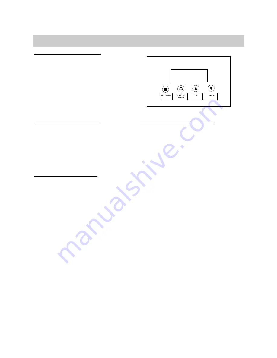
Key Pad Configuration

SETTINGS  This function is to enter the basic set up infor­

mation required at the time of installation. 

MANUAL 
REGEN 

This function is to initiate an immediate or 
delayed manual regeneration. 

DOWN / 
UP 

Increase or decrease the value of the settings 
while in the  programming mode. 

DELAYED REGENERATION

Press and release the MANUAL REGEN. But-
ton to set a delayed regeneration that will 
occur at the regeneration time.  The main 
display page will show DELAYED REGEN ON.  
To cancel press and release the MANUAL RE-
GEN. Button.  The main display page will 
show DELAYED REGEN OFF. 

IMMEDIATE REGENERATION

To start an immediate regeneration (or step 
valve through each position), press and hold 
the MANUAL REGEN. Button for 3 seconds 
(until beeps).  The valve will start an immedi-
ate regeneration.  Press any key to skip to 
the next cycle. 

Manual  Regeneration  (Step  /  Cycle 

1. Plug  the  power  transformer  into  an  ap-

proved power source.  Connect the power 
cord to the valve. 

2. When power is supplied to the control, the 

screen  will  display  “INITIALIZING  WAIT 
PLEASE” while it finds the service position. 

3. Manually  step  the  valve  past  the  BRINE 

position  to  the  BACKWASH  position.    If 
screen  is  locked,  press  SETTINGS  for  3 
seconds  to  unlock.    Press  and  hold  the 
MANUL  REGEN.  Key  for  3  seconds.    Press 
any key to skip the BRINE cycle. 

4. Open  the  inlet  on  the  bypass  valve 

slightly  and  very  slowly  allow  water 
to  enter  the  unit.    (If  the  water  en-
ters too quickly it will push the media 
up  into  the  control  valve  and  get 
plugged).  

5. For  carbon  filters,  once  the  unit  has 

filled  sufficiently  that  water  is  at 
least equal to the height of the top of 
the  media  shut  down  the  water  for 
15  –  20  minutes  for  the  carbon  to 
soak.  Unplug the power cable.  After 

the carbon has soaked for the recom-
mended  time  continue  by  plugging 
the  power  cable  back  in.    For  non-
carbon filters allow unit to backwash 
3-4 minutes or until drain line is clear 
of any fines. 

6. Press any button to advance to the RINSE 

position.  Check the drain line flow.  Allow 
the  water  to  run  for  3-4  minutes  or  until 
the water is clear. 

7. Press any button to advance to the REFILL 

position.  Check that the valve is filling wa-
ter  into  the  brine  tank.  Allow  the  valve  to 
refill  for  the  full  amount  of  time  as  dis-
played  on  the  screen  to  insure  a  proper 
brine solution for the next regeneration. 

8. The valve will automatically advance to the 

SERVICE  position.  Open  the  outlet  valve 
on  the  bypass,  then  open  the  nearest 
treated  water  faucet  and  allow  the  water 
to run until clear, close the tap and replace 
the faucet screen. 

9. Add salt into the cabinet / brine tank. 
10. Program unit. 

Summary of Contents for 785

Page 1: ...ying provided with install kit NSF certified lubricant to all seals 3 This system is not intended for treating water that is microbiologically unsafe or of unknown quality without adequate disinfectio...

Page 2: ...anual must be followed to minimize the risk of electric shock property damage or personal injury Be sure to check the entire unit for any shipping damage or parts loss Also note damage to the shipping...

Page 3: ...Excessive sun or heat may cause distortion or other damage to non metallic parts Properly ground to conform with all gov erning codes and ordinances Use only lead free solder and flux for all sweat so...

Page 4: ...edia Volume Cubic Feet 0 75ft3 1 0ft3 1 5ft3 2 0ft3 3 0 ft3 Filter Tank Size 8x44 9x48 10x54 12x52 14x65 Tank Jacket Media Loaded Yes Yes Yes No No Shipping Weight 50lbs 60lbs 78lbs 95lbs 138 lbs Serv...

Page 5: ...ilitates the removal of iron and manganese by raising the pH This enables an iron filter to be used Periodic backwashing cleans the bed Addi tional media may be required six months to two years after...

Page 6: ...Put the filter in a place water damage is least likely to occur if a leak develops The manufacturer will not repair or pay for wa ter damage A 120 volt electric outlet to plug the in cluded transform...

Page 7: ...pump must be capable of providing the backwash flow rates indicated on page 4 Check Your Pumping Rate Two water system conditions must be checked carefully to avoid unsatisfactory operation or equipm...

Page 8: ...when soldering pipes that are connected to the valve Failure to do this could cause damage to the valve 5 Connect the drain hose 10 ft included to the valve and secure it with a hose clamp also inclu...

Page 9: ...9 Filter Installation...

Page 10: ...locked press SETTINGS for 3 seconds to unlock Press and hold the MANUL REGEN Key for 3 seconds Press any key to skip the BRINE cycle 4 Open the inlet on the bypass valve slightly and very slowly allow...

Page 11: ...3 2 2 2 2 2 2 5 6 6 4 4 3 3 3 3 2 2 2 2 1 1 1 1 6 6 6 4 4 3 3 3 2 2 2 2 1 1 1 1 1 7 6 4 4 3 3 2 2 2 1 1 1 1 1 1 1 1 8 6 4 4 3 2 2 2 2 1 1 1 1 1 1 1 1 9 4 4 3 3 2 2 1 1 1 1 1 1 1 1 1 1 10 4 3 3 2 2 1 1...

Page 12: ...l through the diagnostics press the down or up key To reset the TOTAL REGENS TOTAL GALLONS OVER RUN TO TAL or PEAK flow rates press and hold the MENU until the value changes to zero PARAMETER DESCRIPT...

Page 13: ...to 30 minutes During this time you may hear water running intermittently to the drain Manual Bypass In the case of emergency you can isolate your water filter from the water supply using the bypass va...

Page 14: ...r to determine the expected life of your media bed AC Taste and Odor Filter under normal operating conditions the effective life of the filter media is approximately one to three years depending on th...

Page 15: ...2 Fine gravel 2 Fine gravel 3 Carbon 3 Calcite Once this is done the rag or cork should be removed from the distributor tube Clean off the top of the tank Finally place the control valve on the tank a...

Page 16: ...Main Repair Parts Replacing Drain Line Flow Control DLFC 1 Remove the red clip that secures the drain line elbow 2 Remove the BLFC washer from the elbow fitting 3 Reassemble using the reverse procedu...

Page 17: ...17 Filter Exploded View Brine tank for softener system only...

Page 18: ...18 A A A B D F E A C Main Repair Parts Connectors...

Page 19: ...TOR SET 00 VIOLET 60010130 85HE SEAL SPACER KIT 60010034 INJECTOR SET 0 RED 60010131 85HE DLFC 1 1 5 GPM 60010033 INJECTOR SET 1 WHITE 60010132 85HE DLFC 2 2 0 GPM 60010032 INJECTOR SET 2 BLUE 6001013...

Page 20: ...0 1 5056063 O Ring 78 74 5 33 A21 1 26010103 O Ring 25 3 55 A22 1 7060007 Valve Bottom Connector A23 1 13000426 Screw ST2 9X13 Large Washer A24 2 5031022 O Ring 32 3 A25 1 5031021 O Ring 18 3 A26 1 50...

Page 21: ...21 Power Head Exploded View...

Page 22: ...6 Screw ST2 9X13 Large Washer A24 2 5056139 Washer 3x13 B09 1 5030007 BNT85 Main Gear B10 1 5030005 BNT185 Housing B11 1 5031017 BNT85HE Brine Gear Downflow B12 1 5010023 Magnet 3 2 7 B13 1 5056141 Wa...

Page 23: ...23 Trouble Shooting...

Page 24: ...mineral tank or brine tank to any original equipment purchaser in possession of a tank that fails provided that the water conditioner is at all times operated in accordance with specifications and not...

Reviews: