triggering so that the positive trapezoid output is observed, then set the
square wave generator’s amplitude control (attenuator) for an amplitude of 6
V.
Change the scope vertical sensitivity to 50 mV/div. To prevent scope
overload, clamp the Monitor output signal by moving the LB1502 Clamp
Box switch to the CLAMP position. Adjust the Pole/Zero slider bar for
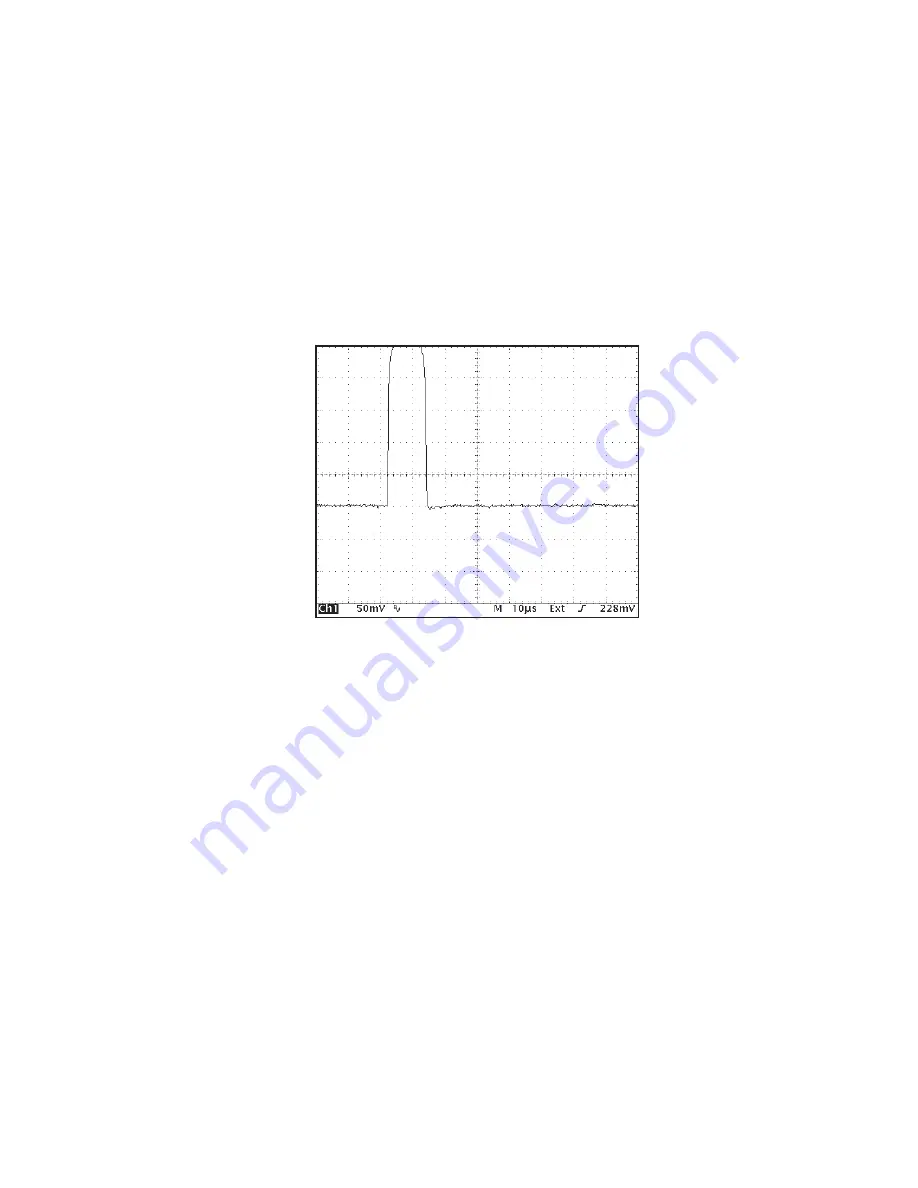
correct pole/zero compensation. Figure 28 shows the correct P/Z setting.
Figures 29 and 30 show under- and over-compensation for the preamplifier decay time
constant. As illustrated in the correct Pole/Zero compensation example, the monitor
output signal should have a clean return to the baseline with no bumps, overshoots or
undershoots.
User’s Manual - ICN 9231014G
67
Pole/Zero Matching - Supplementary Information
Figure 28 Correct Pole/Zero Compensation
Scope:
Vertical: 50 mV/div
Horizontal: 10
µ
s/div


