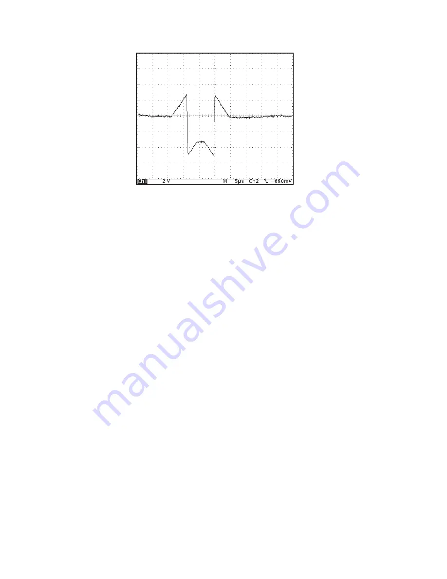
This source requires a high system gain to position its peaks in the mid to upper por-
tion of the selected MCA spectral range. For this case, the baseline or DC component
of the trapezoid signal is large and signal wrapping begins to occur at slightly over 3
volts then jumps down to approximately 5 volts below zero. Even though the Monitor
Output wrapping appears to be significant here, the Trapezoid waveform remains use-
ful when verifying setup and optimizing the Pole/Zero.
The wrapping effect is proportional to the gain setting and also to the filter rise time
selection, as mentioned earlier. In the event it is troublesome, momentarily reduce the
rise time or gain to a lower setting and the wrapping effect will be significantly re-
duced or eliminated. Verify or optimize the setup; when completed, return to the de-
sired rise time and/or gain setting. Again, the MCA spectrum is not affected, due to the
large dynamic range of the 9660’s digital filter.
Note
The optimum Pole/Zero setting is independent of the Filter Rise Time and Flat
Top setting. For further information regarding the effect of “wrap around”
when setting the Pole/Zero, please refer to “Rise Time and Flat Top Adjust-
ments” on page 63.
Using the Monitor Output to Verify System Gain
The 9660 gain settings are calibrated to produce the same system gain (in keV/chan-
nel) as a traditional analog system with the same settings. For a given detector, radia-
tion source and MCA setup (conversion gain, conversion range, etc.), the resultant
MCA spectral peaks will be located in approximately the same MCA channel location
for both the 9660 and the traditional analog system.
User’s Manual - ICN 9231014G
31
Using the Monitor Output to Verify System Gain
Scope:
Vertical: 2 V/div
Horizontal 5
µ
s/div
Figure 18 Output Range Shifted by Detector
Noise


