background image

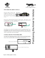
CORRECT

INCORRECT

CORRECT

INCORRECT

Fig. 21

Aligning

Aimer

to

V

ehicle

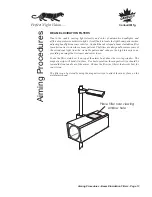
POSITIONING AIMER TO VEHICLE

With


the 

aimer


centered 

in


front


of


the


vehicle

,


choose


two


symmetrical


points


of


the


vehicle


located


at


the


same


height

 off the ground


(i.e.


the


upper


part


of


the


lamps,


strut


bolts,


radiator


support


bolts

, grill work etc.

).

Points


located


too


high,


such


as


the


vehicle


roof,


should


be


avoided:


the


best


accuracy


is


obtained


using


lower


points.

Make sure that plenty of light is on the front of the vehicle. 

Looking


through


the


lateral


alignment


visor,


spot the two points and position


both


points


on


the


visor's


wire,


by


slightly


rotating


the


aimer

 left or right

,


Fig.21.

Aimer is ready to test headlight. Turn on headlights and use internal screen to aim the
light. Correct beam positioning on the aiming screen is explained on the following pages.
Proper aim for high beams, low beams, Euro beams, driving lights, and fog lights are
explained.

Positioning Aimer to Vehicle - Page 11

Canbuilt Mfg.

Perfect Night Vision.....

Summary of Contents for OPT-5405

Page 1: ...Model OPT 5405 Ver 050720 Professional Optical Headlight Aiming System Canbuilt Mfg Perfect Night Vision...

Page 2: ......

Page 3: ...Floor 7 Floor Slope Register 8 Vehicle Preparations 9 Positioning Aimer to Vehicle 10 Beam Slope Compensation 20 Calibrating the aimer 21 Warranty Information 27 Aiming Procedures 12 The Aiming Scree...

Page 4: ......

Page 5: ...of the Standards SAE J599 Aug 1997 andJ600 Feb 1993 Aims allheadlightsincluding Domestic European andAsian typeheadlights Laserguidedfloorslope compensation Simple operation Easilytransportable fromb...

Page 6: ...980 10 mm 1 Flat washer 10 mm Lateral alignment visor Lock unlock mechanism Mast cap Precision floor slope compensation system 7 8 9 10 11 Aimer positioning system Floor slope register Laser guided fl...

Page 7: ...st as shown in fig 2 by pressing trigger lock fig 3 and sliding it down the mast Fig 1 STEP 3 Check that the mast is correctly positioned The aimer head should be parallel to the base fig 4 Tighten th...

Page 8: ...wide slotfaces thefront STEP 5 Install the pointer positioning system using hardware as shown in fig 7 Hardware is attached to the optical aimer head and must be removed for pointer installation fig 6...

Page 9: ...er are located on irregular flats It is recommended not to aim the headlamps on such floors Fig 15 LASER GUIDED FLOOR SLOPE COMPENSATION SYSTEM Position aimer at front of bay Turn on laser by turning...

Page 10: ...n Use the recorded floor slope setting for subsequent uses in the same location Simply set the slope adjustment knob to the previously recorded position priortoaimingheadlights ONCE THE SETTING IS REC...

Page 11: ...adin thevehicleotherthan thedriver Check functioning of any automatic vehicle leveling systems and specific manufacturer s instructions pertaining to vehicle preparation for headlamp aiming Cleanlense...

Page 12: ...that positioning pointer is at center of headlight beam The pointer can be stored as shown with dashed lines inillustration when notinuse Canbuilt Lift Here Professional Optical Headlight Aiming Syste...

Page 13: ...curacy is obtained usinglowerpoints Make sure that plenty of light is on the front of the vehicle Looking through the lateral alignment visor spot the two points and position both points on the visor...

Page 14: ...er scale an aiming test screen compliant with the Standard SAE J599 revisedAug 1997 The beam projections appear on the internal screen of the aimer as they would appear on a screen located 25 feet fro...

Page 15: ...enhance the high intensity zone providing animagethatisclearerand easierto see To use the filter simply set it on top of the aimer body above the viewing window The magnetic strips will hold it in pl...

Page 16: ...djustment Nominal Vertical Aim Line 100 mm 100 mm 100 mm 100 mm 4 4 4 0 4 8 Inspection upper limit Inspection lower limit 4 0 4 4 4 Inspection left limit Inspection right limit 4 0 4 4 4 AIMING LOW BE...

Page 17: ...is should be adjusted to the centerline on the aiming screen The top edgewill normally beeasytolocate DIFFERENT LOW BEAM PATTERNS is highest on the screen There are many different beam patterns used i...

Page 18: ...HEADLIGHTS 4 0 4 4 4 FAIL too far right 0 4 FAIL too high 4 0 4 4 4 4 0 4 FAIL too far left 4 0 4 4 4 Perfect Adjustment FAIL too low 4 0 4 4 4 too low 4 4 0 4 4 4 0 4 4 Page 15 Aiming Procedures Aim...

Page 19: ...on limits for high beam headlamps shall be with the center of the high intensity zone from 100mm 4 up to 100mm 4 down and from 100mm 4 left to 100mm 4 rightonascreenat7 6m 25 4 0 4 4 4 The figure show...

Page 20: ...Inspection limits shaded area for the top edge and center of the high intensity zone of FOG LAMPS AIMING FOG LAMPS The correct aim for fog lamps with symmetrical beams as described in SAE J583 is with...

Page 21: ...pean type low beams are aimed so the cutoff of the illuminated zone is located at the horizontalandbiasedline AIMING EUROPEAN HIGH BEAM HEADLAMPS European high beams are aimed so that the high intensi...

Page 22: ...s that headlights centered 36 48 from the ground must be aimed 2 below the 0 line and headlights mounted 48 54 must be aimed 4 below the 0 line Inspection tolerance isplus or minus 4 TABLE 7 6 m 25 ft...

Page 23: ...urn the laser on and measure the height of the beam from the bottom of the optical aimer head asshown Move the ruler to the end of the optical aimer head to see if the height of the beam is the same I...

Page 24: ...ateral calibration points on the aimer head as shown in drawings below The line in the visor must match the edge of the three aligned holes on the aimer head If the visor is not perfectly aligned turn...

Page 25: ...cle used for the test is more than 36in then a NominalVerticalAimlineatthedistancespecified in theTable1 shallbetraced Performthepreparation forheadlamp aimasdetailed Proceed toaimthelowerbeamasexplai...

Page 26: ...NT OF VEHICLE LOWER BEAM VERTICAL CENTERLINE AHEAD OF LEFT HEADLAMP VERTICAL CENTERLINE AHEAD OF RIGHT HEADLAMP CAR AXIS AIMING the LOWER BEAM HEIGHT OF LAMP CENTERS OR NOMINAL VERTICAL AIM SEE TABLE...

Page 27: ...m instead of the low asareference AIMING HIGH BEAM HEADLAMPS High beam headlamps and auxiliary driving lights are aimed so that the center of the high intensityzoneislocatedatthehorizontalandstraighta...

Page 28: ......

Page 29: ...be repaired or replaced at the option of Canbuilt Mfg 6 Canbuilt will pay for freight charges one way from Canbuilt to purchaser purchaser must pay freight to Canbuilt 7 Proof of purchase must be supp...

Page 30: ...NOTES Canbuilt Mfg Perfect Night Vision...

Page 31: ...the Panther model OPT 5405 Contact your sales representative for information on other high quality automotive repair products from Canbuilt Mfg Please visit our web site at www canbuilt com Canbuilt...

Page 32: ...Professional Model Optical Headlight Aimer Canbuilt Mfg 103 Milvan Dr Toronto Ontario Canada M9L 1Z7 416 749 6555 www canbuilt com Canbuilt Mfg Perfect Night Vision...

Reviews: