RS02250/0717/CD
26
www.cdtechno.com
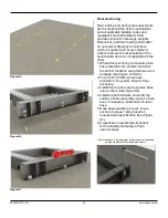
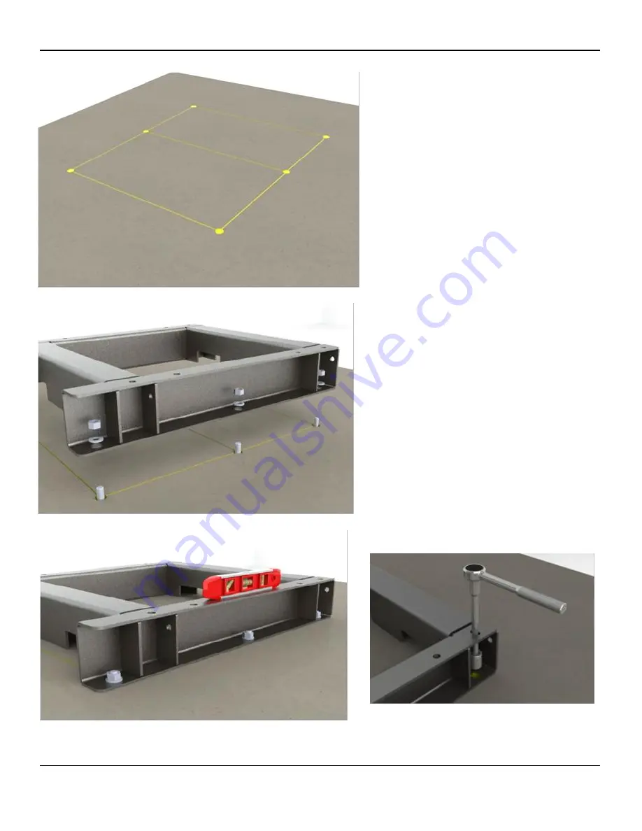
Figure A5
Floor Anchoring
Floor loading and anchoring requirements
are the responsibility of the user/installer
and all applicable building codes and
regulations must be followed. C&D
provides connection drawings, weights,
dimensions, and floor loading information
on our system drawings for reference
which is supplied with every shipment.
Anchor bolts are the responsibility of the
user/installer and are not supplied with the
order.
1. Where floor anchoring is required, place
base assembly into position and mark
the anchor locations using the base as a
template (See Figure A5 & A6).
2. Four
13/16” [20.6mm] holes are
provided in the system base for floor
anchoring.
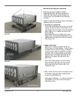
3. Install floor anchors and reposition base
onto anchors (See Figure A6).
4. Install anchor hardware and verify top
surface of base assembly is level in both
axes, if necessary install shims to level
base.
5. Once base assembly is level, torque
anchors to proper rating based on
manufactures specification (See Figure
A7).
6. A level base is particularly important
for the stability and safety of high,
narrow stacks.
If tool clearance is an issue rear anchors can be accessed
using a
standard 3/8” extension as shown.
Figure A6
Figure A7

