RS02109/0814/CD
10
www.cdtechno.com
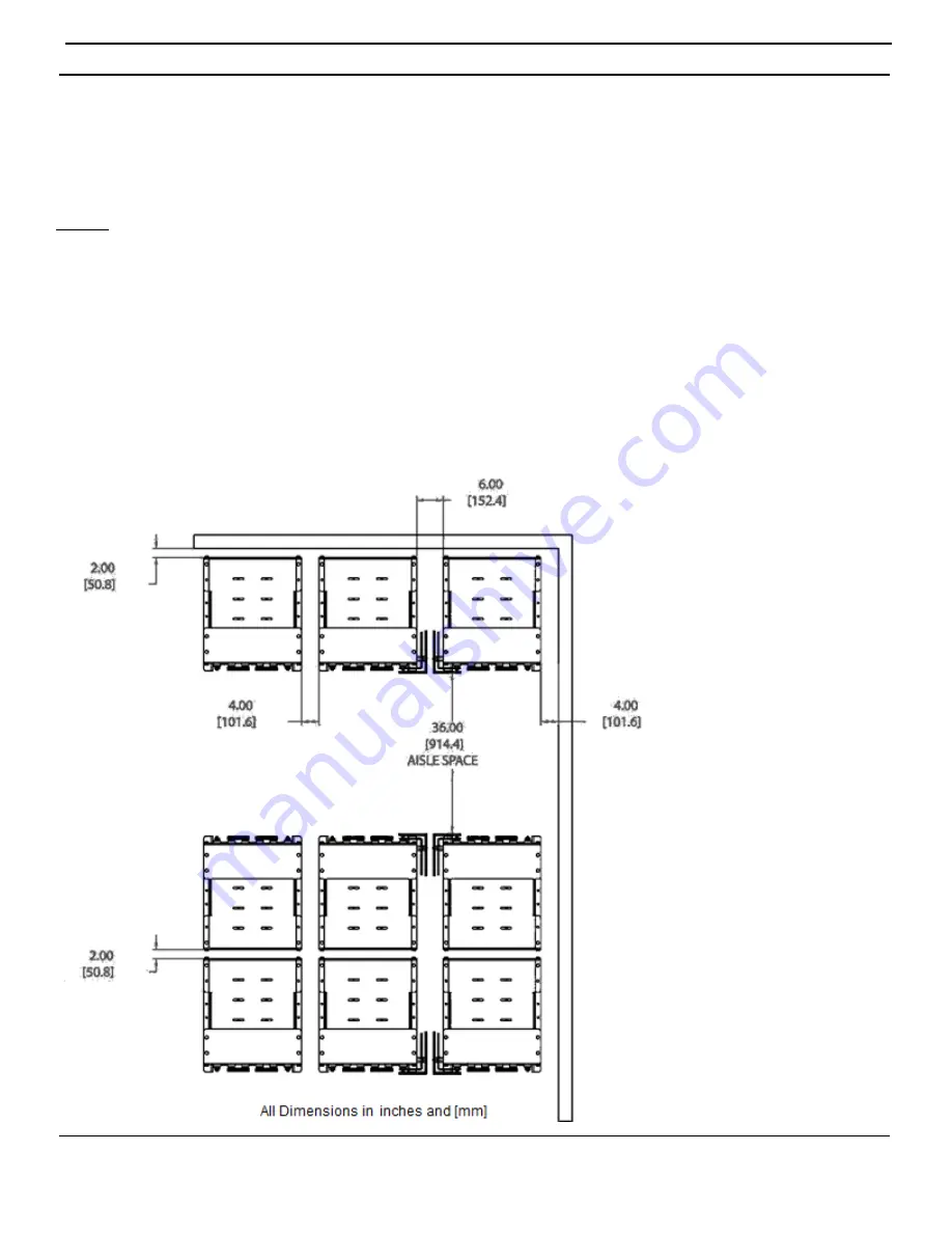
When considering room layouts and determining the necessary floor space required for mounting a given
system the below diagram is a guide to C&D’s recommended system clearances. Should a question or
concern arise please contact your C&D sales representative for further details. Each system is shipped with
an Applications Engineering System layout which goes into further detail on system layouts and floor
anchoring.
Notes:
1. Allow a minimum of 2.00” from the back of any system to a wall or any other obstruction/equipment.
2. Allow a minimum of 4.00” between systems (side to side) where no side termination is being used.
Reference supplied C&D connection diagram for additional details.
3. Allow a minimum of 6.00” between systems (side to side) where side termination is being used.
4. Allow a minimum of 4.00” spacing from any wall/equipment to the side of any system.
5. When installing systems back to back allow a minimum of 2.00” spacing from module to module as
shown in the diagram below.
6. Always allow for a minimum of 36.00” aisle space in front of the system for suitable handling
equipment.
7. There may be a de-rating of anchor bolt load ratings due to the proximity of anchor holes. Reference
anchor bolt manufacturer’s data for additional information.

