7
2.4
REMOVAL OF M-MODULES
To remove an M-Module, first remove all four screws from the holes in the bottom of the
enclosure. Do NOT remove the screws from the top of the M-Module. With several fingers of
one hand, apply an upward pressure to the back of the mating connector. With your other hand,
slowly rock the module from side to side. The module should slowly loosen itself from the
carrier header pins. If the EM405-8 is completely full, a pointed prying bar may be required to
help remove the first module. The point of the prying bar can be placed between the carrier
header and the M-Module to loosen the connection as shown in Figure 4.
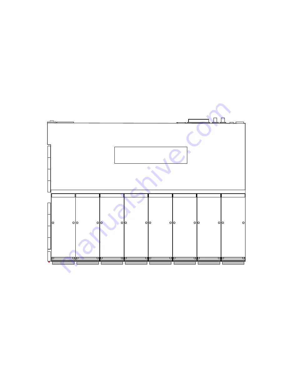
Figure 2. M-Module Configuration Diagram
FA
N
FA
N
FA
N
FA
N
FA
N
FA
N
FA
N
FA
N
INTERNAL ELECTRONICS
(DO NOT REMOVE COVER)
MODULE
0
MODULE
1
MODULE
2
MODULE
3
MODULE
4
MODULE
5
MODULE
6
MODULE
7
C&H Technologies, Inc. <> 445 Round Rock West Drive <> Round Rock, Texas 78681 <> www.chtech.com


