

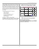


System 236E Installation Instructions
5-051-504-00 Rev B
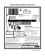
Connect ground wire from door hinge to earth ground
using 16 AWG, green/yellow jacketed, solid-conductor
wire
GENERAL INFORMATION
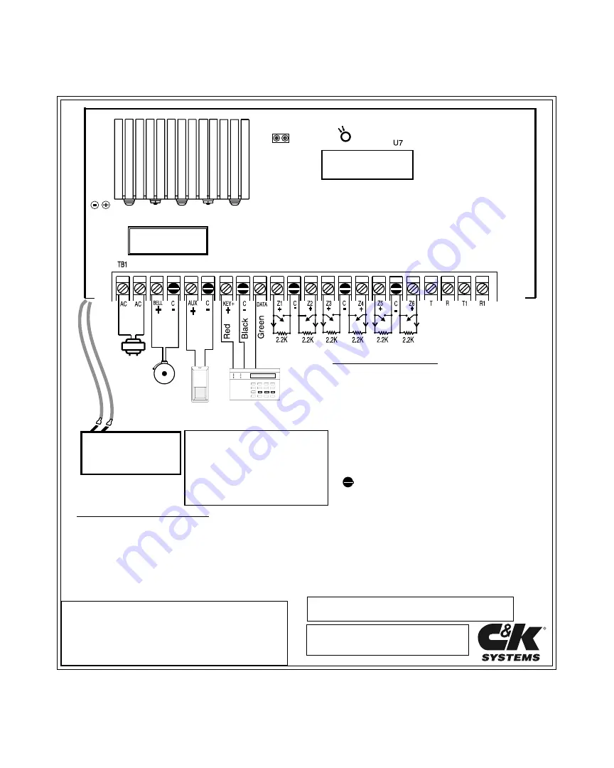
All outputs are power limited
If programmed for EOL or Supervised Loop, the 2.2K
ohm EOL resistor must be at end of circuit
When used as a fire warning system, use a 4-wire
smoke detector (Sentrol #ES-449C) with a Power
Supervisory EOL Relay Module (System Sensor
A77-716 Series) at the end of the detector power
loop. Consider the maximum detector alarm load
when confirming that the total alarm load is less than
800 mA.
are electrically common
Loop voltages:
0.0 - 1.5 VDC = short
1.6 - 3.1 VDC = normal
3.2 - 5.0 VDC = open
16.5 VAC
25 - 40 VA
50 or 60 Hz
AUDIBLE
9.5 - 14 VDC
SWITCHED
AUX POWER
9.3-14.0 VDC
KEYPAD
9.8 - 14.0 VDC
Do not exceed 3 keypads
CAUTION:
Total Power from terminals BELL,
AUX, and KEY+
NOT
to exceed 800
mA, combined.
All power outputs are current limited.
(Also see
NOTE:
below.)
Direct
Conn
JP2
Watch
Dog
DS1
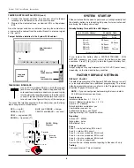
WARNING:
Disconnect AC, Battery, and Phone Cord
BEFORE servicing.
Use FCC compliant RJ-31X
or RJ-38X Plug and Jack
Red = Incoming Ring (R)
Green = Incoming Tip (T)
Gray = Seized Ring (R1)
Brown = Seized Tip (T1)
Blue = Tamper
Orange = Tamper
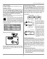
POWER SUPPLY INFORMATION
Use only 12 VDC, 6.5 A-H or 4.0 A-H sealed lead-acid battery
Replace battery every 4 - 6 years with C&K Model 1265 or Model 1240
6.5 A-H standby battery time with 1 keypad is 24 hours at 150 mA
Power demand for AUX POWER, keypads, and sounders not to
exceed maximum ratings.
Install transformer on unswitched power receptacle
Maximum battery charge current = 350 mA
This equipment should be installed in accordance with the
National Fire Protection Association's Standard 72 Chapter 2
(National Fire Protection Association, Batterymarch Park, Quincy,
MA 02269). Printed information describing proper installation,
operation, testing maintenance, evacuation planning and re-
pair service is to be provided with the equipment.
4.0 A-H standby battery time with 1 keypad is 7 hours at 400 mA
NOTE:
Total power from terminals AUX and KEY+
NOT
to exceed 400 mA, combined.
All ratings on this page are in compliance with UL
985, UL 1023, and UL 1635.
12 VDC, 6.5 A-H
or
12 VDC, 4.0 A-H
Sealed Lead-Acid
Trans-
former
Bell Output not to
exceed 600 mA
The control unit shall be checked by a qualified
technician at least every 3 years.


