RCO-6000 l User’s Manual
56
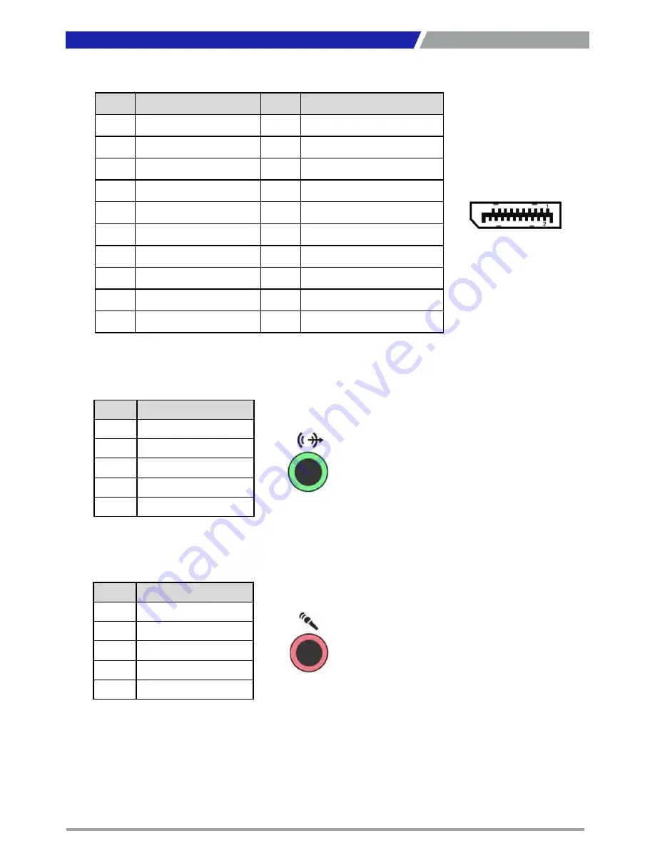
DP2: DisplayPort Connector
Pin
Definition
Pin
Definition
1
DP2_LANE0_P
11
GND
2
GND
12
DP2_LANE3_N
3
DP2_LANE0_N
13
GND
4
DP2_LANE1_P
14
GND
5
GND
15
DP2_AUX_P
6
DP2_LANE1_N
16
GND
7
DP2_LANE2_P
17
DP2_AUX_N
8
GND
18
DP2_HPD
9
DP2_LANE2_N
19
GND
10
DP2_LANE3_P
20
DP2_PWR
SPK_OUT1 : Speaker-out Jack (Green)
Connector Type: 5-pin Phone Jack
Pin
Definition
1
GND
2
OUT_R
3
NC
4
GND
5
OUT_L
MIC_IN1: Microphone Jack (Pink)
Connector Type: 5-pin Phone Jack
Pin
Definition
1
GND
2
MIC_R
3
NC
4
GND
5
MIC_L
Chapter 2: Switches and Connectors
Summary of Contents for RCO-6000
Page 1: ...RCO 6000 Series Superior Fanless Embedded System...
Page 11: ...Chapter 1 Product Introductions...
Page 47: ...Chapter 2 Switches and Connectors...
Page 49: ...RCO 6000 l User s Manual 49 2 1 2 Bottom View Chapter 2 Switches and Connectors...
Page 67: ...Chapter 3 System Setup...
Page 92: ...Chapter 4 BIOS Setup...
Page 116: ...Copyright C T Solution Inc All Rights Reserved www candtsolution com...


