PC300 / PC311E(P) l User’s Manual
21
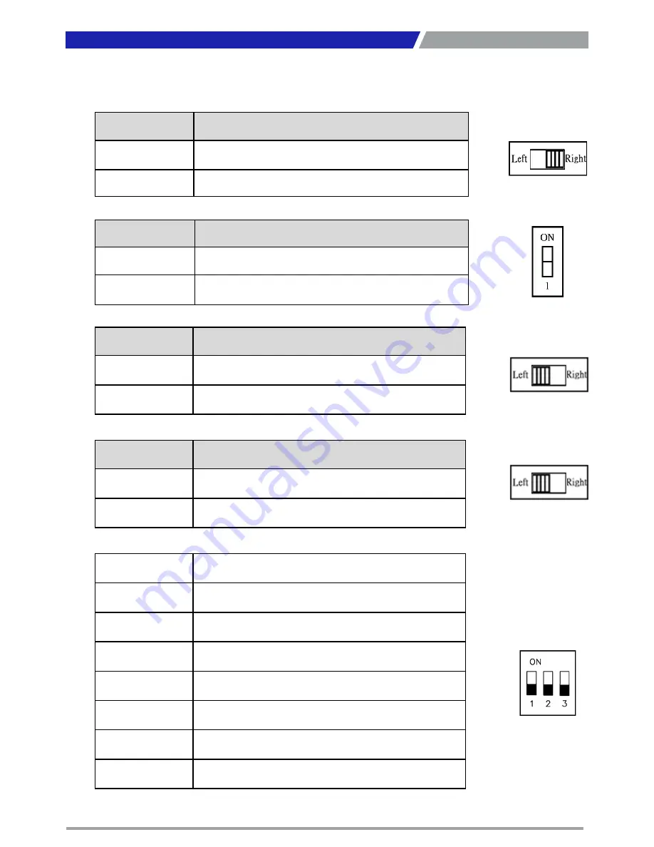
Switch
Definition
1-2 (Left)
AT Power Mode
2-3 (Right)
ATX Power Mode
(
Default
)
2.3 Switches Definitions
AT_ATX1: AT / ATX Power Mode Switch
CLR_CMOS1: Clear BIOS Switch
Switch
Definition
Off
Normal Status (Default)
ON
Clear BIOS
CAR_PWR1: PC / CAR Power Mode Switch
Chapter 2: Switches and Connectors
Switch
Definition
1-2 (Left)
PC Power Mode
(
Default
)
2-3 (Right)
CAR Power Mode
12-24V_SEL1 : Car Power input voltage Switch
Switch
Definition
1-2 (Left)
DC 24V CAR Power Input Mode
(
Default
)
2-3 (Right)
DC 12V CAR Power Input Mode
DELAY_TIME1 : Car power turn off delay time Switch
Switch 1 / 2 / 3
Definition
OFF / OFF / OFF
0 sec.
(
Default
)
ON / ON / OFF
1 min.
ON / OFF / ON
5 min.
ON / OFF / OFF
10 min.
OFF / ON / ON
30 min.
OFF / ON / OFF
1 hour
OFF / OFF / ON
2 hour
Summary of Contents for PC311E
Page 1: ...PC300 Series PC Module...
Page 8: ...Chapter 1 Product Introductions...
Page 17: ...PC300 PC311E P l User s Manual 17 1 4 2 PC311E PC311P Unit mm Chapter 1 Product Introductions...
Page 18: ...Chapter 2 Switches and Connectors...
Page 28: ...PC300 PC311E P l User s Manual 28 Chapter 2 Switches and Connectors...
Page 32: ...Chapter 3 System Setup...
Page 47: ...Chapter 4 BIOS Setup...
Page 73: ...Copyright 2016 C T Solution Inc All Rights Reserved www candtsolution com...


