


Consult the designs in the front pages referenced in the text by
alphabet letters.
Closely follow the instructions set out in
this manual.
All responsibility, for any eventual inconveniences,
damages or fires caused by not complying with the instructions
in this manual, is declined.
Installation
The cooker hood must be placed at a minimum distance of
60 cm from the cooking plane for electric cookers and 65cm
for gas or mixed cookers.
The hood can be installed above these heights but for
optimum performance it should be installed at the distance
quoted for the appropriate heat source.
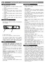
The hood is equipped with a top air outlet
B
(Fig. 2) for
discharge of fumes to the outside (
Ducting version
exhaust pipe and pipe fixing clamps not provided).
Should it not be possible to discharge cooking fumes and
vapour to the outside, the hood can be used in the
filter
version
, fitting an activated carbon filter (in the case of the
model with two suction motors then two active carbon filters
are required), a discharge tube, for the expulsion of fumes,
should be mounted on the connection ring
C
(Fig. 7) situated
on the top of the wall cabinet (discharge tube and fixing
brackets are not supplied).
The models with no suction motor only operate in ducting
mode, and must be connected to an external suction device
(not supplied).
Preliminary information for installation of the hood:
Disconnect the hood during electrical connection, by turning
the home mains switch off.
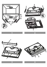
1.
Fix the 2 brackets
D
(Fig. 1) to the side panel of the wall
cabinet (one per side) with 2 screws for each bracket
(align the bracket to lower border).
Position the bracket to touch the back border of the wall
cabinet, considering that the back border of the bracket
corresponds to the back side of the cooker hood;
If the cooker hood is provided with a spacer, in case of
use, move the bracket forward to the same thickness
as the spacer.
Drill a hole on the ceiling of the wall cabinet to pass the
discharge tube and the electrical cable (the quote
indicated in Fig. 1 does not include the eventual spacer).
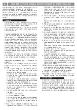
2.
Fix 2 brackets
E
(Fig. 2) to the sides of the cooker hood
(one per side).
a. remove the extractable part of the cooker hood;
b. remove the grease filter/s;
c. fix the brackets with two screws
P
per bracket from
inside the cooker hood, affix them as more as possible
upwards (air exit side) and then serrate the screws.
3.
Fix the aesthetic mask
Q
from the inside of the cooker
hood using two screws, (if supplied - Fig. 3 the
L
tabs
present on the body of the cooker hood serve as further
fixing for the mask and should be visible once the mask
has been fitted) and then finally affix the spacer
M
with
three Clips from the external part of the cooker hood (if
supplied - Fig. 4).
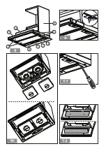
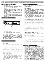
4.
Insert the cooker hood in the wall cabinet, ensuring to
position the cooker hood bracket
E
above the wall
cabinet bracket
D
(Fig. 5).
Thread the electric cable through the appropriate
perforation.
5.
Block the cooker hood with two screws on the frontal part
(Fig. 5 one per side).
6.
Connect the cable to the electrical mains, only when the
installation is completed.
7.
If the cooker hood should not touch perfectly with the
lower border of the wall cabinet then regulate by
loosening the screws
P
of the brackets
E
mounted on
the cooker hood (Fig. 2), it will be possible to regulate
the perfect matching of the cooker hood and wall cabinet,
once regulated tighten the screws.
8.
Regulate the gliding of the extractable drawer in relation
to the depth of the wall cabinet by acting on the two skirting
boards
F
(Fig. 6).
In this way it will be possible to place the front in line with
the wall cabinet (Fig. 6).
a. Loosen the screws on the skirting board
F
;
b. Move the ledges backwards or forwards depending
on requirement.
c. Lock in the screws on the ledges.
9.
Install a discharge tube on the connection ring
C
supplied,
preferably with a diameter equivalent to the connection
ring (Fig. 7). the discharge tube should be sufficiently
long to reach outside (Suction version) or the ceiling of
the wall cabinet (Filter version).
10.
Fix the connection ring
C
(snap into place), at the upper
exit of the cooker hood.
To ease the installation, the ring is equipped with an index
G
that should correspond to the appropriate guide
H
placed on the upper air exit.
11.
Complete the installation of the discharge tube.
12.
Re-install the grease filters, connect the cooker hood to
the electrical mains and check the perfect operation.
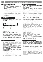
Electrical connection
The electrical tension must correspond to the tension noted
on the label placed inside the cooker hood. Connect the
electrical plug, where provided, to the an easily accessible
outlet in conformity with local standards in force.
Where an electrical plug is not provided (for direct connection
to electrical network) place a standards approved bipolar
switch with an aperture distance of not less than 3mm
(accessible) from the contacts.
INSTRUCTION ON MOUNTING AND USE
GB
Summary of Contents for CBT62
Page 2: ...Ø 150mm Ø 150mm D min 135 87 1 2 3 4 B E E P M Q L ...
Page 3: ...D E 5 6 7 F G H C ...
Page 4: ...Fig 9 Fig 12 8 6 3 5 Fig 8 Fig 10 Fig 11 4 1 4 7 2 8 9 11 10 12 ...
Page 34: ......
Page 35: ......
Page 36: ...LI2BAA Ed 01 04 ...


