


ENGLISH
INSTALLATION
The hood is available in the ducting version (air evacuated outside the room) or the filtering version (air recirculated
inside the room).
1) The following operations are essential for assembly: Install a proper wiring system. If your apparatus is to
be assembled as a Ducting appliance, you must first make the air venting hole and get a proper pipe to connect
the hole to the flange of the hood; use an outlet pipe with: - minimum indispensable length; - minimum possible bends
(maximum angle of bend:90°); - certified material (according to the State); - an as smooth as possible inside. It is
also advisable to avoid any drastic changes in pipe cross-section (recommended diameter: 125 mm). For air evacuation
to the outside, follow all the instructions given on the “Warnings” sheet.
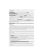
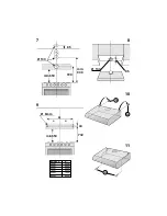
Make an air evacuation hole in the wall (diameter 133 mm) as shown in Fig. 1 which gives all the measurements required
for the various possible installations.
2) Some models are fitted with an upper air vent (Fig. 2B) and a rear air vent (Fig.2A) closed by a plate that
must be removed if you wish to use it. Fit the flange (C) on the vent used; if you use the rear vent, close the
upper one with the cap (E) to be ordered from your dealer.
Some models are fitted with 2 air vents, one in the upper part (Fig. 2B) and one at the rear (Fig. 2A), which you can use
as required. Fit the flange (C) on the vent used and close the other one with the cap (E).
In the filtering version, you do not need to close any vent, but position the lever correctly (see point 7).
3) Wall mounting : Drill 4 holes in the wall using the measurements shown in Fig. 3 and insert the screw anchors;
take 2 of the supplied screws (Fig. 4G) and screw them into the uppermost anchors without tightening them. Attach
the hood to the 2 screws and, working from inside, fully tighten them. Complete mounting by inserting and tightening
the other 2 screws H (Fig. 4).
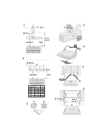
4) Mounting under a wall unit: If the ducting version of the hood is mounted with the air outlet in the upper opening
(Fig. 2B), before mounting, drill a 133 mm diameter hole in the wall unit (Fig. 5).
Drill 4 holes in the wall unit using the measurements shown in Fig. 6. Attach the hood with 4 screws working from inside
the wall unit.
5) For the ducting version: connect a flex tube to the hood flange using a metal retainer clamp. The tube and clamp
are not included in the supply.
6) Make the electrical connection.
7) CHECK THAT THE DUCTING-FILTERING LEVER IS IN THE RIGHT POSITION: The lever is found on the motor
unit and must be positioned on the symbol (
P
) in the case of installation in ducting version, on the symbol (
Q
) in
the case of installation in filtering version (Fig. 7).
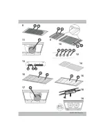
8) PAY ATTENTION TO THE CHARCOAL FILTER/S (A) - Fig. 8-9-10-11: One or more charcoal filters are required for
the filtering version. If they are not yet installed in the hood, fit it/them as follows depending on the model you have purchased:
- if the hood is fitted with round charcoal filters (Fig. 11R), fit the charcoal filter by turning it anticlockwise. - if the hood
is fitted with a panel charcoal filter (Fig. 8A or 9A or 10A), position the charcoal filter inside the hood and fit the 2 filter
clips (M) to lock the charcoal filter. The ducting version does not require the charcoal filter/s, therefore, if already fitted
in the hood remove it/them.
OPERATION
The hoods are provided with the following type of controls:
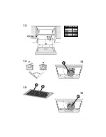
Controls of Fig. 12: A
= light switch.
B
= first speed motor ON/OFF switch.
C
= second speed switch.
D
= third
speed switch.
E
= warning light: indicates motor operation.
Controls of Fig. 13:
A
= light switch; position 0: light off; position 1: light on.
B
= motor switch; position 0:
motor off; position 1-2-3: motor first, second and thrid speed motor on.
C
= warning light: indicates motor operation.
Grease filter/s
: Depending on the version, the hood features different types of grease filters:
Modular metal filters (of the type shown in Fig. 14): these are metal filters and must be periodically cleaned, depending
on extent of operation (at least every two months). Wash the filters with neutral detergent.
Panel type metal filter (as shown in Fig. 15N): this is a metal filter and is positioned inside the metal grid; the filter
must be periodically cleaned, depending on extent of operation (at least every two months). Wash the filter with
neutral detergent. Remove the 2 filter retainers (M) and the metal panel filter.
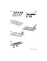
Panel type synthetic filter (as shown in Fig. 16P): this filter is made of white synthetic fibres and is located inside
the metal grid; it cannot be cleaned, but must be replaced from time to time according to use (at least every two
months). Remove the 2 filter retainers (M) and the synthetic panel filter.
Charcoal filter/s
: The charcoal filters must be replaced periodically depending on their use, on average every 6 months.
Remove the charcoal filters as follows, depending on the model you have purchased:
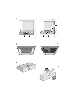
- if the hood is fitted with round charcoal filters (Fig. 17R), remove the charcoal filter by turning it clockwise.
- if the hood is fitted with a panel charcoal filter (Fig. 8A or 9A or 10A), remove the 2 filter clips (M) and then remove the
charcoal filter.
Lighting:
- To replace the incandescent lamps remove the light fitting after unscrewing the setscrew “A” (Fig. 18).
Replace with lamps of the same type.
- To remove the halogen lamps , unscrew the ring nut by turning it anticlockwise (Fig. 19). Replace with lamps of the same
type.
WARNING: Do not touch the new lamp with bare hands. Should the halogen lamps not work after replacing them,
cut the power to the hood for a few seconds.


