CANDY HOOVER GROUP S.R.L. • Via Comolli 16 • 20861 Brugherio (MB) Italy
BUILT-IN GAS ON GLASS COOKING HOBS
INSTALLATION ADVICES - INSTRUCTIONS FOR THE USE
GB
•
CVG6PX SASO
CVG938WPB SASO
Page 1: ...CANDY HOOVER GROUP S R L Via Comolli 16 20861 Brugherio MB Italy BUILT IN GAS ON GLASS COOKING HOBS INSTALLATION ADVICES INSTRUCTIONS FOR THE USE GB CVG6PX SASO CVG938WPB SASO...
Page 2: ...2 2...
Page 3: ...Please preserve this booklet carefully It may be useful in future either to yourself or to others in the event that doubts should arise relating to its operation This appliance must be used only for t...
Page 4: ...ve a more pronounced temperature perception with some components although these parts are within the limits allowed by the norms The complete safety of the appliance also depends on the correct use we...
Page 5: ...ordance to health and environmental protection regulations ensuring in particular that all potentially hazardous parts be made harmless especially in relation to children who could play with unused ap...
Page 6: ...ceramic hob Do not allow heavy or sharp objects to drop on the glass ceramic hob Do not scratch the hob with sharp objects Don t use the hob as a work surface WARNING If the hob is cracked or otherwis...
Page 7: ...dance with the wiring rules WARNING The appliance and its accessible parts become hot during use Care should be taken to avoid touching heating elements Children less than 8 years of age shall be kept...
Page 8: ...8 8 ADVICE ADVICE for the for the INSTALLER INSTALLER...
Page 9: ...personal injury or damage This appliance shall only be serviced by authorised personnel Always disconnect the appliance from mains power supply before carrying out any maintenance operations or repai...
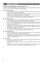
Page 10: ...w the base of the cooktop as indicated in fig 1 1c If the base of the cooktop is accessible through a cupboard or drawer space after installation or if the oven installed below the cooktop has a cooli...
Page 11: ...ide models 900 510 840 1 X 8 mm 2 X 4 mm 650 mm 500 mm 450 mm E F D G B A C Fig 1 1a Fig 1 1b Cooktop installed G 40 mm Space for connections Clearance Door Thermal protection barrier The thermal prot...
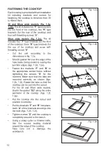
Page 12: ...erlay the junction edges figs 1 2d 1 2e Fasten the brackets F and R to the appropriate socket holes without tightening the screws S for the moment Make sure that the tabs are mounted correctly as show...
Page 13: ...13 13 30 mm min 40 mm max 40 mm min S A R G G1 30 mm min 40 mm max S A F G G2 40 mm min Fig 1 2h Fig 1 2i Rear Fixing Brackets Front Fixing Brackets Fig 1 2f G2 G2 Fig 1 2g G G2 G G2...
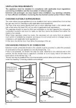
Page 14: ...hat they cannot be blocked from either the inside or the outside When these openings cannot be made the necessary air can come from an adjacent room which is ventilated as required as long as it is no...
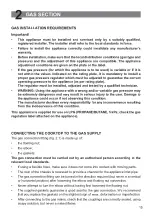
Page 15: ...viced only by a suitably qualified registered installer The installer shall refer to the local standards in force Failure to install the appliance correctly could invalidate any manufacturer s warrant...
Page 16: ...rners or moving parts as these may cause abrasion Use a single flexible hose only never connect the cooktop with more than one flexible hose The flexible hose can easily be inspected along its entire...
Page 17: ...NECESSARY FOR GAS COMBUSTION 2 m3 h x kW BURNERS Air necessary for combustion m3 h Auxiliary A 2 00 Semi rapid SR 3 36 Rapid R 6 00 Double ring compact MW 7 00 Double ring DCS 7 60 GAS MAINTENANCE LU...
Page 18: ...etre are marked on the body of each injector REPLACEMENT OF THE INJECTORS OF THE COOKTOP BURNERS To replace the injectors proceed as follows Remove pan supports and burners from the cooktop Using a wr...
Page 19: ...t even with a quick turn from the maximum position to that of minimum The flame adjustment is done in the following way Turn on the burner Turn the tap to the MINIMUM position Take off the knob With a...
Page 20: ...with the letter E or the earth symbol or coloured green yellow connect the blue wire to the terminal marked with the letter N or coloured black connect the brown wire to the terminal marked with the l...
Page 21: ...hazard To connect the supply cable Unhook the terminal board cover by inserting a screwdriver into the two hooks A fig 3 1 Open the cable gland by unscrewing screw F fig 3 2 unscrew the terminal scre...
Page 22: ...22 22...
Page 23: ...23 23 ADVICE ADVICE for the for the USERS USERS...
Page 24: ...24 24 FEATURES AND TECHNICAL DATA 1 Fig 1 3 Fig 1 4 Fig 1 1 1 1 2 2 3 3 5 5 4 2 10 8 7 11 9 8 11 9 8 7 Fig 1 2 1 2 3 4 10 9 8 7...
Page 25: ...25 25 7 10 12 9 8 1 1 4 6 6 3 3 3 6 2 2 2 4 4 1 Fig 1 5 Fig 1 7 Fig 1 6 10 9 12 8 7 12 7 9 8 10...
Page 26: ...has a safety valve system fitted the flow of gas will be stopped if and when the flame should accidentally go out CAUTION If the burner is accidentally extinguished turn the gas off at the control kno...
Page 27: ...or maintaining boiling conditions of liquids To reduce the gas flow to minimum rotate the knob further anti clockwise to point the indicator towards the small flame symbol Other intermediate operatin...
Page 28: ...lighted taper 2 Wait for a few seconds after the gas burner has been lit before letting go of the knob valve activation delay 3 Adjust the gas valve to the desired position If the burner flame should...
Page 29: ...mum diameter 6 cm minimum diameter 12 cm only for the model in fig 1 1 at pag 24 only for the models with Double ring compact or Double ring burner and with wok pan adapter supplied It is important th...
Page 30: ...ing on models Warning Do not use woks without this special wok stand correctly in place Do not use the wok stand for ordinary flat bottomed saucepans IMPORTANT The special grille for wok pans MUST BE...
Page 31: ...31 31 MODELS WITH DOUBLE RING BURNER Fig 2 5b Fig 2 5a CORRECT WRONG...
Page 32: ...eed 50 minutes operation IMPORTANT WARNINGS Do not operate the cooking zones without pans or when the pans are empty Use pans with a diameter suited to the size of the burner see chapter CHOICE OF THE...
Page 33: ...33 33 Fig 2 7 IMPORTANT Flame spreaders must not be used on the burners Risk of breaking the glass hob...
Page 34: ...or this type of product category However special care should be taken around the underneath of the appliance as this area is not designed or intended to be touched and may contain sharp or rough edges...
Page 35: ...the gas taps must be carried out by specialist personnel only In the event of operating faults in the gas taps call the Service Department IMPORTANT WARNING NEVER unscrew the burner plate fixing screw...
Page 36: ...the electric ignition do not use it when the burners are not in place CORRECT REPLACEMENT OF THE AUXILIARY SEMI RAPID AND RAPID BURNER depending on your model your cooktop may only have some of these...
Page 37: ...37 37 S F C T Fig 3 2 Fig 3 3 S T T S Fig 3 4 MODELS WITH DOUBLE RING COMPACT BURNER MODELS WITH DOUBLE RING BURNER Fig 3 5...
Page 38: ...38 38 A B Fig 3 6 Fig 3 7...
Page 39: ...an cause serious problems The pan supports shall be level and must not rotate Fig 3 8 AUXILIARY SEMI RAPID AND RAPID BURNER depending on your model your cooktop may only have some of these burners DOU...
Page 40: ...ng from printing or transcript errors contained in this brochure We reserve the right to carry out modifications to products as required including the interests of consumption without prejudice to the...