background image

8

CANNON

®

 CT-1000 Constant Temperature Bath

Revision 3.1a—February, 1998; 

CANNON

®

 Instrument Company

P.O . Box 16 • State College, PA • USA

11. Pull out the drawer using the handles provided, disconnecting the two

connection cables as you do so.

CAUTION

You will need to pull the AC line (power) cord through the rear panel
opening as you remove the drawer—you should not try to remove the cord
until you loosen the screw securing the power cord to its connection on the
back of the drawer).

12. Press down or pull up on the plastic release bars on either side of the

drawer track to release the drawer, then pull the drawer completely
free of the unit and set it aside.

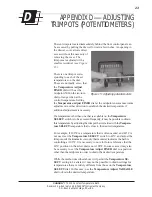
13. When the drawer is removed, locate the four 1/4-20 set screws

visible at the top of the drawer opening underneath the bath.

14. Turn the set screws

clockwise with the
Allen wrench (in-
cluded with the bath)
until the top of the jar
forms a tight seal with
the covers (see

Figure 10

). Make

sure you tighten the
set screws uniformly
so the jar remains
level.

15. Run the AC cord through the rear panel opening

16. Replace the drawer in the slide tracks and push the drawer back into

its opening. Insert the two plugs into the rear of the drawer assembly.

Motor-stirrer

Complete the assembly of the bath, including the motor-stirrer installation,
per the instructions below:

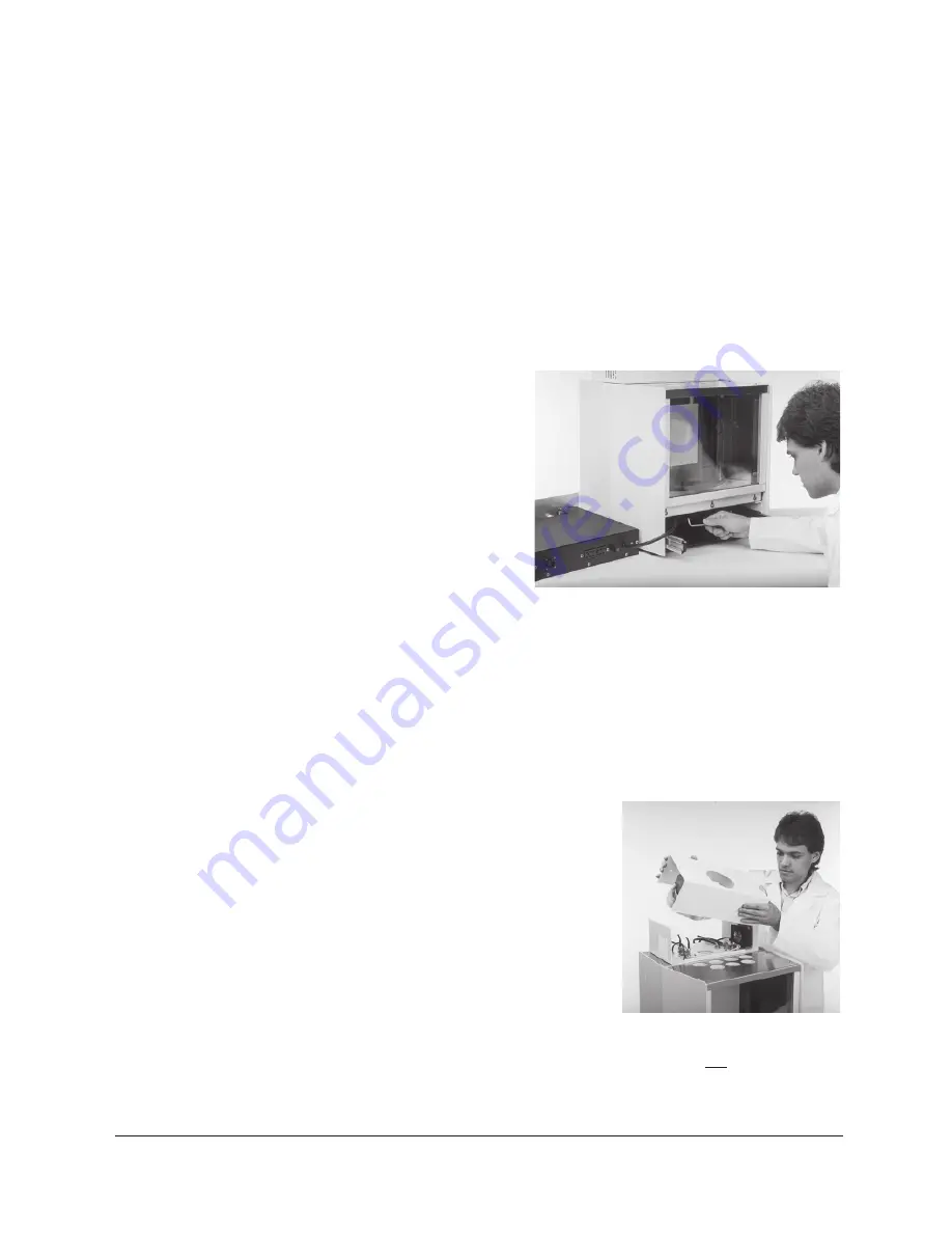
1. Take the motor/stirrer from its

box. Remove the two screws on
the top heater housing and lift off
the housing (see 

Figure 11

).

2. After checking the impeller blades

to make sure that the flat sections
all lie in the same plane (see
Appendix B), insert the motor
stirrer in the opening provided (see

Figure 12

, next page).

NOTE

To keep from accidentally bending the motor shaft, do not hold the motor
assembly by the shaft. Use care when inserting the motor shaft and
impeller to prevent damage to delicate components.

FIgure 10: Adjusting seal with set screws

Figure 11: Removing housing

Summary of Contents for CT-1000

Page 1: ...ting viscometer tubes thermometers 9 Filling the bath 10 Draining the Bath 11 3 BATH OPERATION 13 Turning on the CT 1000 13 Setting the bath temperature 14 Fixed temperature adjustments 14 Variable te...

Page 2: ...PA USA F APPENDIX F THERMOMETRY 27 KINEMATIC VISCOSITY AND TEMPERATURE 27 ASTM THERMOMETER TABLES 28 ASTM D 445 CHECKING THE ICE POINT 29 NBS MONOGRAPH 150 REPAIRING SEPARATED MERCURY COLUMNS 31 G WAR...

Page 3: ...bility and ease of use it is also suitable for any other application where temperatures must be maintained within close tolerances Temperature range The CANNON CT 1000 will maintain temperatures of 20...

Page 4: ...ps provide glare free illumination of the bath A solid state control circuit equipped with a stainless steel encased thermistor provides proportional temperature control Amotor driven stirrer ensures...

Page 5: ...ns who use the CT 1000 should follow these basic safety procedures Do not place the CT 1000 system on an unstable cart or stand The CT 1000 should be placed on a stable laboratory table or bench If an...

Page 6: ...4 CANNON CT 1000 Constant Temperature Bath Revision 3 1a February 1998 CANNON Instrument Company P O Box 16 State College PA USA This page intentionally left blank...

Page 7: ...st screwdriver Allen wrench seven hole covers rubber thermometer holder and instruction manual Box 2 contains the bath housing including the electronics drawer Box 2 also contains a smaller box with t...

Page 8: ...ove the front top cover and rear top cover see Figure 4 and 5 Use caution when removing the rear top cover because the tempera ture control probes and heating elements are attached to it Glass jar ins...

Page 9: ...binet 5 Lower the glass jar into the cabinet so it seats evenly on the rubber support ring see Figure 8 6 Unwrap the two glass panels Place the thinner of the two piece of glass in the slot closest to...

Page 10: ...with the bath until the top of the jar forms a tight seal with the covers see Figure 10 Make sure you tighten the set screws uniformly so the jar remains level 15 Run the AC cord through the rear pane...

Page 11: ...before filling the bath with fluid Inserting viscometer tubes thermometers The top cover of the CT 1000 contains seven apertures 51 mm 2 in diameter for the insertion of viscometer tube holders Two a...

Page 12: ...to add fluid until the bath liquid level has risen to approxi mately 40 mm 1 5 of the top of the jar 4 Turn the instrument power ON and incrementally heat the bath to desired control temperature while...

Page 13: ...le container to hold all of the liquid drained from the bath approximately 20 22 liters or 4 5 5 gallons Make sure that the bath liquid is within 10 C of ambient temperature Then insert a tube into th...

Page 14: ...12 CANNON CT 1000 Constant Temperature Bath Revision 3 1a February 1998 CANNON Instrument Company P O Box 16 State College PA USA This page intentionally left blank...

Page 15: ...ters to match their typeface on the panel Turning on the CT 1000 1 Turn the Power BATH switch on Figure 14 A NOTE The bath heaters will not be activated if there is no liquid in the bath Figure 14 Bat...

Page 16: ...will glow continuously until the bath temperature is approximately that selected with the Temperature SELECT switch when the light will begin to blink The light above the Temperature Adjust control w...

Page 17: ...nd allow several minutes for the bath to equilibrate NOTE If a desired bath temperature is within two or three degrees of one on the Temperature SELECT dial it is sometimes possible to attain the tem...

Page 18: ...16 CANNON CT 1000 Constant Temperature Bath Revision 3 1a February 1998 CANNON Instrument Company P O Box 16 State College PA USA This page intentionally left blank...

Page 19: ...Check for working motor by connecting to outlet with the proper voltage see motor label for correct voltage Check connections for sensors on rear panel Check temperature setting it must be above exis...

Page 20: ...18 CANNON CT 1000 Constant Temperature Bath Revision 3 1a February 1998 CANNON Instrument Company P O Box 16 State College PA USA This page intentionally left blank...

Page 21: ...r shaft run out and impeller blade alignment by placing the motor on a soft surface with impeller facing up Connect the motor to the appropriate AC power source and observe the impeller and shaft If r...

Page 22: ...ame side of a shaft as the first mark and is about the same length the bending was not great enough to alter the condition and should be repeated with more force applied If the mark has shifted to the...

Page 23: ...rovides a list of operating temperature ranges and some liquids suitable for use in these ranges C 0 0 2 o t C 0 0 1 S N O I T P O D I U L F H T A B e r u t a r e p m e T C e g n a R s d i u q i L h t...

Page 24: ...ed Because in some cases there is a tendency for algae formation some degree of water treatment may be necessary Water can be used at temperatures close to the boiling point but water replenishment to...

Page 25: ...other than one that is available on the Temperature SELECT switch is to be accessed frequently it may be possible to obtain this temperature by adjusting the trimpot that coincides with the Tempera t...

Page 26: ...24 CANNON CT 1000 Constant Temperature Bath Revision 3 1a February 1998 CANNON Instrument Company P O Box 16 State College PA USA This page intentionally left blank...

Page 27: ...10 LAMINATEDSAFETYGLASS P27 1320 PLATEGLASS P27 2190 LIGHTEDSWITCHROCKER120V P27 2220 PANELMOUNTLED P27 2230 TEMPERATURERESETSWITCH P27 2230 11 LAMPRESETSWITCH P27 2250 SOLIDSTATERELAY25A P27 2280 BAL...

Page 28: ...26 CANNON CT 1000 Constant Temperature Bath Revision 3 1a February 1998 CANNON Instrument Company P O Box 16 State College PA USA This page intentionally left blank...

Page 29: ...ter CANNON Instru ment Company recommends the use of a calibrated ASTM kinematic viscosity thermometer ASTM Thermometers Each ASTM kinematic viscosity thermometer measures only 3 degrees on a scale su...

Page 30: ...vailable from CANNON Instrument Company ASTM CENTIGRADE THERMOMETERS TYPE CATALOGUE RANGE 74C 9311 K47 55 4 to 52 6 C 73C 9311 K45 41 4 to 38 6 C 126C 9311 K77 27 4 to 24 6 C 127C 9311 K81 21 4 to 18...

Page 31: ...83 5 to 88 5 F 28F 9311 L10 97 5 to 102 5 F 46F 9311 L45 119 5 to 124 5 F 29F 9311 L17 127 5 to 132 5 F 47F 9311 L52 137 5 to 142 5 F 48F 9311 L59 177 5 to 182 5 F 129F 9311 L99 197 5 to 202 5 F 30F 9...

Page 32: ...ewar vessel with the crushed ice and add enough distilled and preferably precooled water to form a slush Do not float the ice Place the thermometer into the slush packing the ice gently around the ste...

Page 33: ...e of centrifu gal force usually serves to unite the mercury in the bulb Care must be taken to warm the top of the bulb first so pressures in the bulb due to expanding mercury may be relieved B If ther...

Page 34: ...of the bulb by rotating the thermometer and tapping it against the palm of the hand When the entire surface has been washed rotate the bubble to the top of the bulb and reunite the mercury as describe...

Page 35: ...damages or any damage to plant personnel equipment or products directly or indirectly resulting from the use or misuse of any product sold by the Company except as set forth in and limited by the fore...

Page 36: ...2139 High Tech Road State College PA 16803 USA Please include the following Required information The Return Authorization number RA The name and telephone number of the person at your company to conta...

Reviews: