background image

14

si compression assembly

 the cylindrical shape of the toP CaP fits snugly within the carbon steering tube inside diameter 

(i.D.), supporting the steerer from the clamping force of the stem.   it must fit snugly inside the 

i.D. of the steerer.   

How to install the assembly

1.  assemble the fork, headset, spacers, and stem.  make sure that the stem bolts are loose.

2.  set up the compression assembly.  “reaDy to insert”  above.  the length should be about 

48mm as shown above.  you can do this by  unthreading the top cap from the expander and 

then threading it back on about 6-7 turns. the expanding parts should not be expanded.

3.   insert the si compression assembly into the fork steerer.  it should slide in snugly; the toP 

CaP closely fitting the steerer inside diameter.

4.   insert a 5mm allen key through the access hole in the toP CaP and into the eXPanDer Bolt.  

tighten the expander by turning clockwise to 6.8nm, 5 ftlbs.

5.  to set bearing preload, insert a 6mm allen key  into the hex shape  in the toP CaP iteself.    

turn the entire toP CaP clockwise to increase preload.  turn counter-clockwise to decrease 

preload.    

6.  When the headset preload is correct, align handlebar and tighten the stem fork clamp bolts 

to the torque specified for the stem.  Consult the stem since torque values are often marked 

on the stem, or consult the manufacturer’s instructions.

WARNINGS

USE ONLY ORIGINAL EQUIPMENT CANNONDALE SI COMPRESSION ASSEMBLY.    

Do not 

replace it with a star nut or use any other compression or expanding wedge assembly.   

DO NOT INSTALL HEADSET SPACERS ON TOP OF THE STEM.  

installing spacers above the 

stem will raise the toP CaP inside the steerer removing necessary support for the  steerer 

tube wall.  When stem bolts are tightened. the steerer tube can be damaged.  

PLACE HEADSET SPACERS ONLY BETWEEN THE HEADTUBE AND THE BOTTOM OF THE 

STEM. 


YOU CAN BE  SEVERELY INJURED, PARALYZED OR KILLED IF YOUR IGNORE THESE 

WARNINGS.


Summary of Contents for Slice Carbon

Page 1: ...le routing 6 SEAT POST 8 Saddle Position Angle 8 80mm MINIMUM INSERT 9 Cutting the Seat Post 9 Seat Post Parts 10 Changing Saddle Position 11 SI BOTTOM BRACKET SHELL 12 Compatibility 12 Bearings 9 SI...

Page 2: ...ry to the owner WARNING This supplement may include procedures beyond the scope of general mechanical aptitude Special tools skills and knowledge may be required Improper mechanical work increases the...

Page 3: ...orter frame life over more frame weight and a longer frame life 4 you are choosing light weight over more dent resistant or rugged frames that weigh more All frames that are very light need frequent i...

Page 4: ...a rough abusive or go for it riding style buy heavy duty components Readandfollowthecomponentmanufacturers warnings and instructions Protect From Extreme Temperatures Protect your carbon bike from ext...

Page 5: ...ider Repainting Or Refinishing You should not paint over the existing finish refinish or repaint your bike The carbon fiber composites making up the frame are held together by some extremely strong bo...

Page 6: ...and front derailleur cables exiting the down tube 2 are routed through the bottom bracket cable guide 3 The top tube guide is removable so that brake cable may be routed inside the tube The guide is...

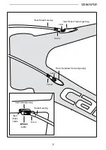
Page 7: ...120849 PDF Ferrule Ferrule Rear Brake Housing Rear Brake Frame Opening Cable Cable Front Derailluer Frame Opening KP063 Top Tube Opening Guide Rear Brake Cable Brake Housing Ferrule...

Page 8: ...nd 10 The water bottle cage bracket parts can only be used with saddle in the TRIATHLON position shown above Two water bottle cages may be mounted on the sides of the seat post or a single cage can be...

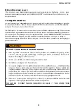
Page 9: ...r permanent marker WARNINGS TO AVOID SERIOUS SEAT POST OR FRAME DAMAGE 1 After any crash fall or impact remove and inspect the seat post for damage e g cracks scratches scrapes gouges splintering If d...

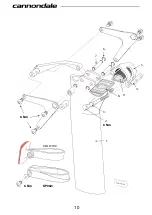
Page 10: ...10 6 Nm 6 Nm 6 Nm KP062 1 2 3 4 5 6 7 8 9 FORWARD REFLECTOR...

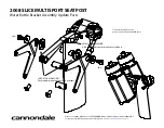
Page 11: ...with post 2008 SLICE MULTISPORT SEATPOST Water Bottle Bracket Assembly Update Parts Please consult the Cannondale SLICE CARBON Owner s Manual Supplement 120849 PDF for seat post installation and servi...

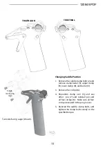
Page 12: ...lamp bolts 2 and remove clamp barrel 3 upper clamp 9 lower clamp 8 and barrel 4 3 Remove the circlips 6 4 Reposition clamp over 5 and use other pin 7 and reinstall pin and all four circlips 6 Make sur...

Page 13: ...MACHINE THE BOTTOM BRACKET SHELL FOR ANY REASON Doing so can result in serious damage and possibly a ruined bike frame SI Tools KT011 is a bearing removal tool KT010 is a set of bearing installation...

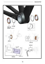
Page 14: ...120849 PDF 13 QC616 KB6180 KT011 KT010 KF365 groove DRIVE SIDE KT013 8mm KP018 ceramic TOOL Loctite 609 green ADAPTER TOOL BB SHELL...

Page 15: ...hten the expander by turning clockwise to 6 8Nm 5 ftLbs 5 To set bearing preload insert a 6mm allen key into the hex shape in the TOP CAP iteself Turn the entire TOP CAP clockwise to increase preload...

Page 16: ...e Thread on TOP CAP Do not grease 5mm EXPANDER BOLT 6 8N m 5 Ft Lbs 6mm TOP CAP EXPANDER EXPLODED VIEW READY TO INSERT MAXIMUM STACK HEIGHT Measure from the top edge of the headtube to the bottom edge...

Page 17: ...same or new Clean dropout and inspect carefully for any cracks or damage Clean surfaces and apply a light film of bike grease to the dropout to minimize any noise or creaking that might result from v...

Page 18: ...er 2 from the frame 3 Install a serrated washer 3 onto the brake bolt and mount the brake onto the adapter Tighten the brake recessed nut 4 to the brake manufacturer s recommended torque 4 Apply greas...

Page 19: ...h cm M 9 0 10 5 12 5 14 5 17 STACK cm 49 4 50 9 52 9 54 8 57 2 REACH cm 37 1 39 8 40 7 41 7 42 5 Headset Compression Cannondale SI Compression Assembly KP017 Seatpost Minimum Insert Depth 80mm Seat Bi...

Page 20: ...UIDE SLICE AERO ORDER HEADSET FORK PARTS KB002 KIT HEADSET SI CRB W 15 TC QC778 BRAKE BOLT 35mm KP017 SI COMPRESSION ASSY ORDER SI BB30 BOTTOM BRACKET QC616 SI CIRCLIPS QTY 2 KB6810 SI BEARINGS QTY 2...

Page 21: ...mm Rd SRM KA019 BB CDALE Si 68X104 CERAMIC ORDER SI CARBON QC781 CRANKSET CRB 2PC 39 53 170 QC782 CRANKSET CRB 2PC 39 53 172 QC783 CRANKSET CRB 2PC 39 53 175 QC784 CRANKSET CRB 2PC 34 50 170 QC785 CRA...

Reviews: