background image

13

134911 Rev 1.

ENGLISH

SYNAPSE - OWNERS MANUAL SUPPLEMENT

SiSL Compression Assembly - 

K35058

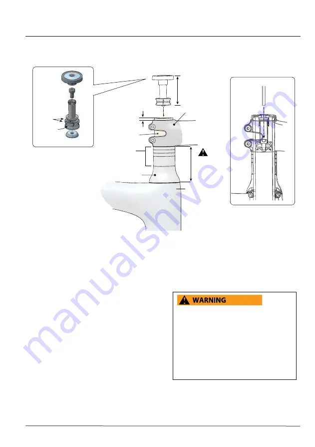
 CAP

EXPANDER BOLT

STEM

FORK STEERER

HEADSET TOP CAP

HEADSET SPACERS

LOWER CONE

UPPER CONE

O-RING

WEDGES

3 mm

5

55mm

Maximum 

Stack

Height

45

mm

Set-Up Length

4 Nm

Exploded Parts View

EXPANDER BOLT

Installation 

1.  Assemble the fork, headset, spacers, and stem into 

the head tube.  The fork steerer is to extend 3mm 

above the top of the stem.

2.  Lightly tighten the stem bolts. 

3  Set-up the compression assembly to 45mm length.  

Adjust the  length by threading the cap on the 

upper cone.  

4.  Insert the compression assembly into the steerer 

tube. 

5.  Insert an 4mm Allen key through the  hole in 

the cap and into the expander bolt.   Tighten the 

expander bolt to 4 Nm.

6.    Set bearing preload.  Insert a 5mm allen key into the 

cap.   Turn the entire top cap clockwise to increase 

bearing preload. Turning it counter-clockwise will 

decrease the preload. 

7.  When the headset preload is set, turn the stem 

to align the handlebar with the front wheel and 

tighten the stem clamp bolts to the torque specified 

for the stem. Consult the stem manufacturer’s 

instructions.  The torque values for components are 

often marked on the part. 

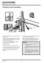
 The installation and adjustment to be performed by 

a professional bike mechanic.  Incorrect installation 

can result damage leading to a accident. 

DO NOT EXCEED THE MAXIMUM STACK HEIGHT 

(55mm) OR LOCATE SPACERS ON TOP OF THE 

STEM.    

YOU  CAN BE SEVERELY INJURED, PARALYZED OR 

KILLED IN AN ACCIDENT IF YOU IGNORE THESE 

WARNINGS.

Summary of Contents for Synapse HM

Page 1: ...0 Visits Hanzepoort 27 7570 GC OLDENZAAL Netherlands Tel 41 61 551 14 80 Fax 31 54 151 42 40 WWW CANNONDALE COM 2017 Cycling Sports Group SYNAPSE Owner s Manual Supplement 134911 Rev 1 SYNAPSE OWNER S...

Page 2: ...134911 Rev 1 SYNAPSE OWNERS MANUAL SUPPLEMENT 134911 Rev 1 SYNAPSE OWNERS MANUAL SUPPLEMENT...

Page 3: ...Acrobat PDF versions of any manual supplement from our website http www cannondale com Your Authorized Cannondale Dealer To make sure your bike is serviced and maintained correctly and that you protec...

Page 4: ...you to read PART II Section D Inspect For Safety in your Cannondale Bicycle Owner s Manual BEFORE you ride YOU CAN BE SEVERELY INJURED PARALYZED OR KILLED IN AN ACCIDENT IF YOU IGNORE THIS MESSAGE In...

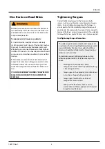
Page 5: ...orrect tightening torque for the fasteners bolts screws nuts on your bicycle is very important to your safety Correct tightening torque for the fasteners is also important for the durability and perfo...

Page 6: ...e or cage can result in damage threaded inserts due to the leverage on a very small area In a crash certainly the last thing you should be worried about is saving the threaded inserts in your frame Ho...

Page 7: ...face or cut the head tube bearing cups When removing adapters bearings or cup from extra care must be used so that the tool used to drive out the bearing is not located on any part a bonded cup FRAME...

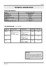
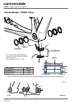
Page 8: ...180 KP249 BLK BB30A KT010 KT011 CK3588U00OS Non Drive Side Drive Side groove Drive Side The small hole in the cable guide cover is to allow any accumulated water inside the frame to drain out Check to...

Page 9: ...ket shell for any reason Repeated removal and reinstallation of BB components could result in damage to the shell and is not recommended Damage caused by improper installation removal is not covered u...

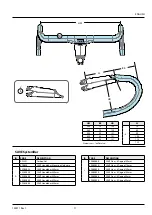
Page 10: ...K 7 5 3 0 H H 7 3 2 9 H 7 0 2 8 H L 27 0 10 6 H H 27 2 10 7 H 27 5 10 8 H M 6 0 2 4 H 5 5 2 2 H 4 5 1 8 H H N 6 0 2 4 5 6 2 2 5 6 2 2 H 5 8 2 3 H H O 51 0 20 1 53 0 20 9 55 0 21 6 57 0 22 5 59 0 23 2...

Page 11: ...inder out of the top of the seat tube See inset A NOTICE Use only a 25 4mm seat post Do not use shims or adapters Do not force a seat post into the frame Frame Size cm Maximum Seatpost Depth mm 44 100...

Page 12: ...n the underside of the stem place items 5 and 6 in the orientation shown inset B torque markings facing out DO NOT use or substitute other fasteners for any reason Apply carbon gel KF115 to the stem b...

Page 13: ...gree 110mm K2802820 SAVE Stem 6 Degree 120mm K2802830 SAVE Stem 6 Degree 130mm K2802880 SAVE Stem 6 Degree 80mm K2802890 SAVE Stem 6 Degree 90mm SAVE SystemBar ID CODE DESCRIPTION KF115 Carbon Gel K28...

Page 14: ...e 0 8 degree range Left handlebar Both the ra ramp angle and the da drops angle are 5 degrees Handlebar pitch is measured where the hands are placed The rl reference line passes through the chrd chord...

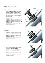
Page 15: ...the cap and into the expander bolt Tighten the expander bolt to 4 Nm 6 Set bearing preload Insert a 5mm allen key into the cap Turn the entire top cap clockwise to increase bearing preload Turning it...

Page 16: ...of the battery surface with a clean lint free shop towel Also clean the inside of the seat post Position the three O ring on the label surface as indicated Insert the batter and O rings into the botto...

Page 17: ...ap 3 starting from the back and working forward SRAM eTap Hook the rear of the guide into the DT port and then continue to push the guide base 2 in the DT port a Make sure the forward tab is hooked un...

Page 18: ...Guide F K32048 Shift And Brake Grommets G CK3578U00OS Synapse Crb FD 1X Cover CK3598U00OS Synapse Crb FD Hanger H KP302 Dropout Cable Stop 20X I KP419 Der Hanger X12 ID CODE DESCRIPTION K35018 1 1 8...

Page 19: ......

Page 20: ...0 Visits Hanzepoort 27 7570 GC OLDENZAAL Netherlands Tel 41 61 551 14 80 Fax 31 54 151 42 40 WWW CANNONDALE COM 2017 Cycling Sports Group SYNAPSE Owner s Manual Supplement 134911 Rev 1 SYNAPSE OWNER S...

Reviews: