EdgeAccess
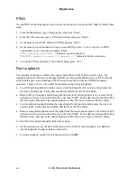
The transmission laser in a 3240S turns on automatically when it receives power. To measure the
output power, follow these steps:
1. Clean the connectors on the fiber optic test cable before plugging it in to the Tx connector on
the 3240S.
2. Warm up each component for at least 30 minutes.
3. Set the optical power meter to the proper wavelength.
4. Wait two or three minutes for the power reading to stabilize, and then read the output power.
5. Subtract out the test cable loss, then record the power level and compare it to the value on the
performance sheet for that particular 3240S. Measurement tolerance is +/-0.5 dBm.
Note: When referencing optical power levels with numerical values less than zero, the reading
closer to zero is the greater value; for example, -17 dBm is greater than -20 dBm.
6. If the reading is out of range, repeat the measurement with a different test cable. If the power
level is still not within range, call Technical Support.
If you know the link attenuation, subtract that value from the 3240S Tx output value to determine the
power expected at the remote cable end, which is the input power at the remote receiver, and skip this
section. Otherwise, continue these steps to use the 3240S to measure the link attenuation.
7. At the local site, connect the fiber link cable to Tx on the 3240S.
8. At the remote site, set the optical power meter to the proper wavelength and connect it to the fiber
link cable.
9. Record the optical power level and compare it with the sensitivity level listed on the data sheet
for the link fiber type.
10. Calculate the optical loss:
(Local Receiver level) - (Remote Transmit level) = (Local link loss)
(Remote Receiver level) - (Local Transmit level) = (Remote link loss)
The remote link loss, in dB, must not exceed the limit for Rx sensitivity listed on the data sheet
for the remote unit.
Note: If you cannot determine the Rx sensitivity, contact Canoga Perkins Technical Support for
assistance.
11. Repeat this process at the other site.
12. If the optical cable loss figure exceeds the optical link loss budget specified for the modem, set
the optical power switch for the modem(s) to HI and repeat the power check.
4-2 3240
S Fiber-Optic Multiplexer
Summary of Contents for 3240S
Page 1: ...Model 3240S SNMP Managed T1 E1 Fiber Optic Multiplexer User Manual...
Page 2: ......
Page 4: ......
Page 6: ......
Page 12: ......
Page 20: ...EdgeAccess 2 8 3240S Fiber Optic Multiplexer...
Page 30: ......
Page 31: ......
Page 32: ......
Page 46: ......
Page 47: ......
Page 48: ......
Page 49: ......


