3. OPERATION AND TIMING
COPYRIGHT © 2001 CANON INC. CANON CLC1000/1000S/3100 REV.2 MAY 2001 PRINTED IN JAPAN (IMPRIME AU JAPON)
3-122
G. Controlling the Transfer Unit Charging Mechanism
1. Outline
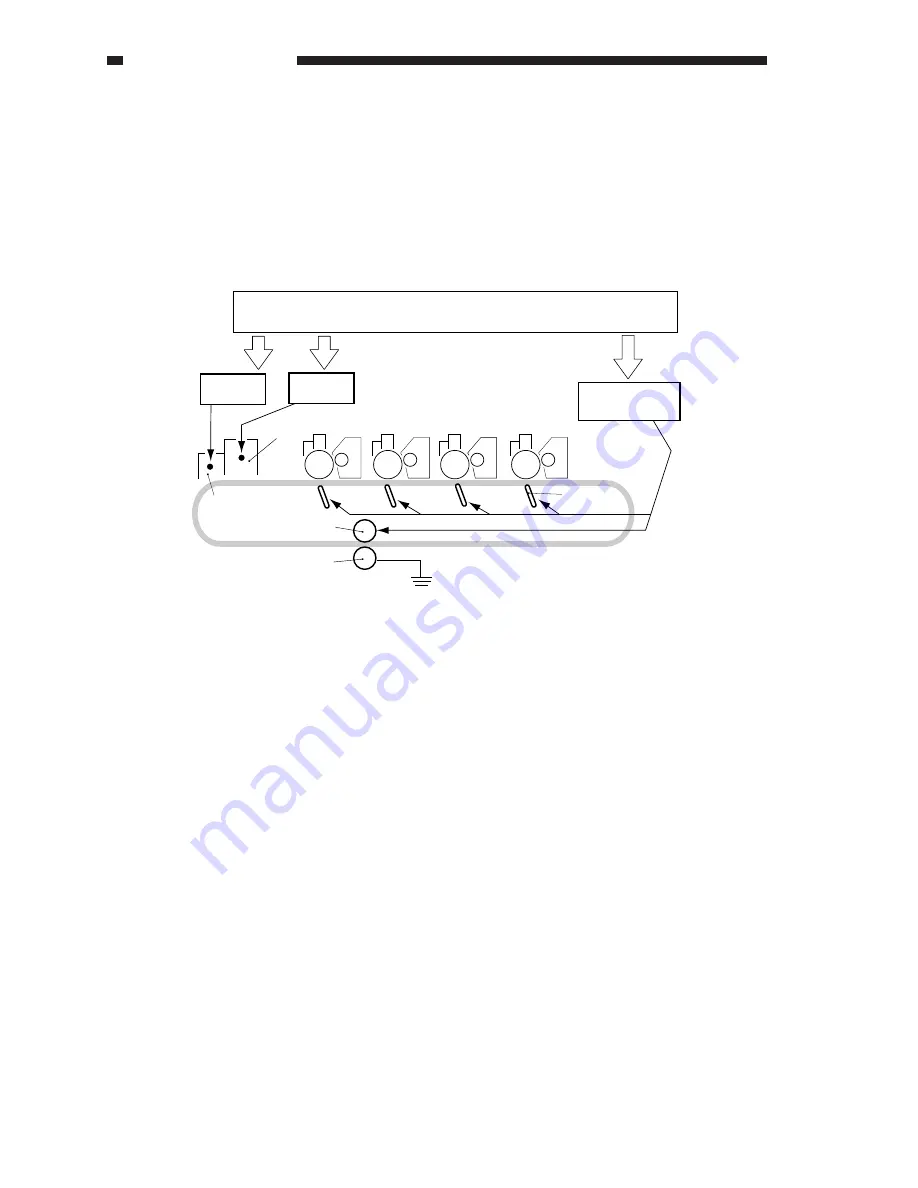
Figure 3-554 shows the construction of the transfer unit. The transfer current to the transfer blade, static
eliminating current to the internal static removing roller, and the charging current to the separation charging
corona wire and the pre-fixing charging corona wire are all controlled by the control signals from the DC
controller. An AC bias and a DC bias are applied to the separation corona wire; only a DC bias is used for all
others.
Figure 3-554
HVT1
Transfer
blade
DC controller PCB
HVT5
HVT4
External static
removing roller
Internal static
removing roller
Pre-fixing charging
assembly
Separation charging assembly
Summary of Contents for 1000S
Page 12: ......
Page 30: ......
Page 44: ......
Page 86: ......
Page 254: ......
Page 372: ......
Page 374: ......
Page 418: ......
Page 438: ......
Page 442: ......
Page 754: ......
Page 764: ......
Page 766: ......
Page 840: ...0501GR PRINTED IN JAPAN IMPRIME AU JAPON This publication is printed on 100 reprocessed paper ...


