3. OPERATION AND TIMING
COPYRIGHT © 2001 CANON INC. CANON CLC1000/1000S/3100 REV.2 MAY 2001 PRINTED IN JAPAN (IMPRIME AU JAPON)
3-178
G. Fixing/Delivery Assembly
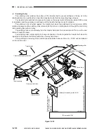
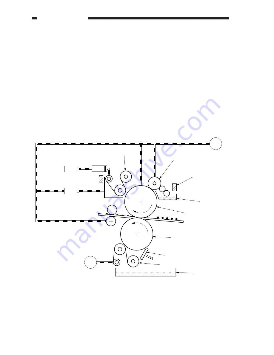
1. Outline
The following loads are driven by the fixing motor (M9).
• Upper fixing roller
• Lower fixing roller
• Delivery roller
• Oil applying roller
• Upper fixing web (locking)
To ensure proper fixing when making two-sided copies or copying on transparencies or to suit various
copying modes, the CLC1000 controls the fixing speed over six settings.
The upper roller and the lower roller are each equipped with a fixing cleaning web. The upper fixing web
is driven by the upper fixing web take-up solenoid (SL3), and the lower web is driven by the lower fixing web
motor (M30).
In addition, the lower fixing roller is equipped with a spring locking type cleaning blade. The separation
claw used to prevent wrapping of paper round the lower fixing roller is operated to move away from the lower
fixing roller by the drive of the separation claw solenoid (SL15) to prevent damage to the lower fixing roller.
Figure 3-646
M9
Fixing motor
Upper fixing web
take-up solenoid
SL3
SL4
One-way clutch
Upper fixing web
Oil applying roller
Oil level sensor (PS6)
Upper oil pan
Upper fixing roller
Lower fixing roller
Oil removing blade
Lower fixing web
Lower oil pan
Lower fixing web motor
Upper fixing web releasing solenoid
Web length sensor (PS36)
M30
Summary of Contents for 1000S
Page 12: ......
Page 30: ......
Page 44: ......
Page 86: ......
Page 254: ......
Page 372: ......
Page 374: ......
Page 418: ......
Page 438: ......
Page 442: ......
Page 754: ......
Page 764: ......
Page 766: ......
Page 840: ...0501GR PRINTED IN JAPAN IMPRIME AU JAPON This publication is printed on 100 reprocessed paper ...


