COPYRIGHT © 2001 CANON INC. CANON CLC1000/1000S/3100 REV.2 MAY 2001 PRINTED IN JAPAN (IMPRIME AU JAPON)
3-179
3. OPERATION AND TIMING
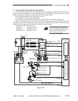
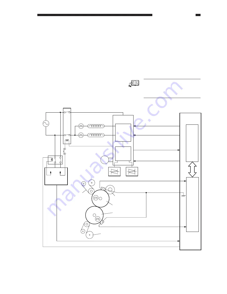
2. Controlling the Fixing Roller Temperature
The upper fixing roller and the lower fixing roller are each heated by a fixing heater (H1: 700W, H2:
500W). The surface temperature of the upper fixing roller is monitored by the thermistor THM1, and the
surface temperature of the lower roller is monitored by the thermistor THM2.
If the surface temperature of the fixing roller is too high,
→
The resistance of the thermistor decreases.
→
The voltage of the fixing roller surface temperature detection signal (THM1, THM2) lowers.
Based on the voltage value, the CPU on the DC controller PCB uses the upper fixing heater drive signal
(UHON) and the lower fixing heater drive signal (LHON) to control the fixing heaters so that the surface
temperatures of the upper roller and the lower roller will be specific values.
• Upper/lower fixing roller (common)
Copying
controlled to 180°C
During STBY
controlled to 180°C
During pre-heat
controlled to 180°C
Figure 3-647
M30
DC controller
PCB
CPU
Upper fixing heater drive
signal (UHON)
Lower fixing heater drive signal
(LHON)
Triac error detection signal (TERR*)
Lower fixing web motor drive signal
(M30D)
Upper fixing roller surface temperature detection signal (THM1)
Lower fixing roller surface temperature detection signal (THM2)
Power to DC controller PCB
Power-off signal (PWOFF*)
AC driver
PCB
Upper fixing heater triac (TR2)
Lower fixing
heater triac (TR1)
Upper fixing thermistor (THM1)
Oil applying roller
Upper fixing roller
Upper fixing web
Lower fixing roller
Lower fixing thermistor (THM2)
Lower fixing web
DC power supply
PCB (DCP1)
Power switch
(SW2: NC)
Lower fixing
web motor
Lower fixing heater (H2)
Fixing lever
Switch
(SW5: NO)
Upper fixing heater (H1)
Thermal switch (TP2)
Thermal switch
(TP1)
Relay (RL1: NO)
H2
H1
TP1
TP2
+24V
+24V
Current
detection
circuit
Thermistor error detection circuit
Triac
short-circuit
detection
circuit
J2213H-10
J2213H-11
J2213H-9
J2213H-6
J2209A-9
J2209A-8
J2209A-10
J2209B-12
REF.
When the fixing lever is shifted to
draw out the fixing assembly, the fix-
ing lever switch (SW5) cuts off
power to the fixing heater.
Summary of Contents for 1000S
Page 12: ......
Page 30: ......
Page 44: ......
Page 86: ......
Page 254: ......
Page 372: ......
Page 374: ......
Page 418: ......
Page 438: ......
Page 442: ......
Page 754: ......
Page 764: ......
Page 766: ......
Page 840: ...0501GR PRINTED IN JAPAN IMPRIME AU JAPON This publication is printed on 100 reprocessed paper ...


