4. MECHANICAL SYSTEM
4-72
COPYRIGHT © 2001 CANON INC. CANON CLC1000/1000S/3100 REV.2 MAY 2001 PRINTED IN JAPAN (IMPRIME AU JAPON)
VII.HOPPER SYSTEM
A. Hopper Assembly
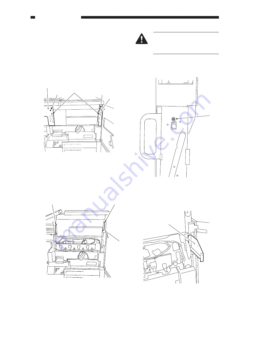
1. Removing the Hopper Assembly
1)
Remove the hopper left/right cover [1] (screw
[2]), and remove the two fixing screws [3] of
the hopper assembly.
Figure 4-701A
2)
Hold the left and right grips [4], and while
pulling to the front, lift the hopper assembly.
Figure 4-702A
3)
Remove the screw [5] from the right grip
assembly.
Figure 4-703A
4)
Install the hopper middle position metal fixing
[6] (left, right).
Figure 4-704A
Make a visual check to be sure that
the locking mechanism under the
hopper assembly is securely en-
gaged.
[3]
[1]
[2]
[2]
[1]
[4]
[4]
[5]
[6]
Summary of Contents for 1000S
Page 12: ......
Page 30: ......
Page 44: ......
Page 86: ......
Page 254: ......
Page 372: ......
Page 374: ......
Page 418: ......
Page 438: ......
Page 442: ......
Page 754: ......
Page 764: ......
Page 766: ......
Page 840: ...0501GR PRINTED IN JAPAN IMPRIME AU JAPON This publication is printed on 100 reprocessed paper ...


