4. MECHANICAL SYSTEM
4-84
COPYRIGHT © 2001 CANON INC. CANON CLC1000/1000S/3100 REV.2 MAY 2001 PRINTED IN JAPAN (IMPRIME AU JAPON)
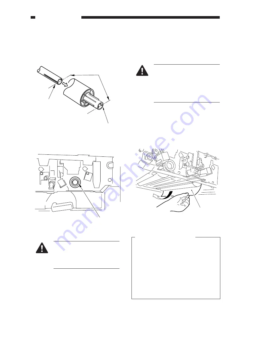
3)
Match the two bosses [3] found on the inner
side of the flange shaft of the photosensitive
drum with the grooves [4] of the drum shaft as
shown.
Figure 4-912A
Figure 4-913A
4)
Fix the developing assembly in place with the
positioning pin.
5)
Set the process unit in the copier.
6)
Secure the positioning pin with screw (w/
spring).
You must lift the developing assem-
bly and move it away from the pho-
tosensitive drum when rotating the
photosensitive drum to prevent
damage to the drum.
7)
Slide out the transfer unit, and remove the
drum protection sheet [5] in the direction of
the arrow.
Store away the drum protection sheet for
future use.
When setting the process unit in the
copier, make sure that the bosses
inside the photosensitive drum
flange and the grooves in the drum
shaft are matched. Take care not to
force the process unit to avoid
scratching the surface of the drum.
Points to Note When Handling
the Drum Protection Sheet
• Do not touch the face that will come into
contact with the drum.
• Put it in a plastic bag to avoid contact with
dust and oil.
• If it must be rolled, be sure that the face
that will come into contact with the drum
is inside.
• Be sure to dry-wipe the drum contact
face with lint-free paper before using it
again.
[4]
[3]
Slit and boss
matched.
[4]
[5]
Figure 4-914A
Summary of Contents for 1000S
Page 12: ......
Page 30: ......
Page 44: ......
Page 86: ......
Page 254: ......
Page 372: ......
Page 374: ......
Page 418: ......
Page 438: ......
Page 442: ......
Page 754: ......
Page 764: ......
Page 766: ......
Page 840: ...0501GR PRINTED IN JAPAN IMPRIME AU JAPON This publication is printed on 100 reprocessed paper ...


