COPYRIGHT © 2001 CANON INC. CANON CLC1000/1000S/3100 REV.2 MAY 2001 PRINTED IN JAPAN (IMPRIME AU JAPON)
3-13
3. OPERATION AND TIMING
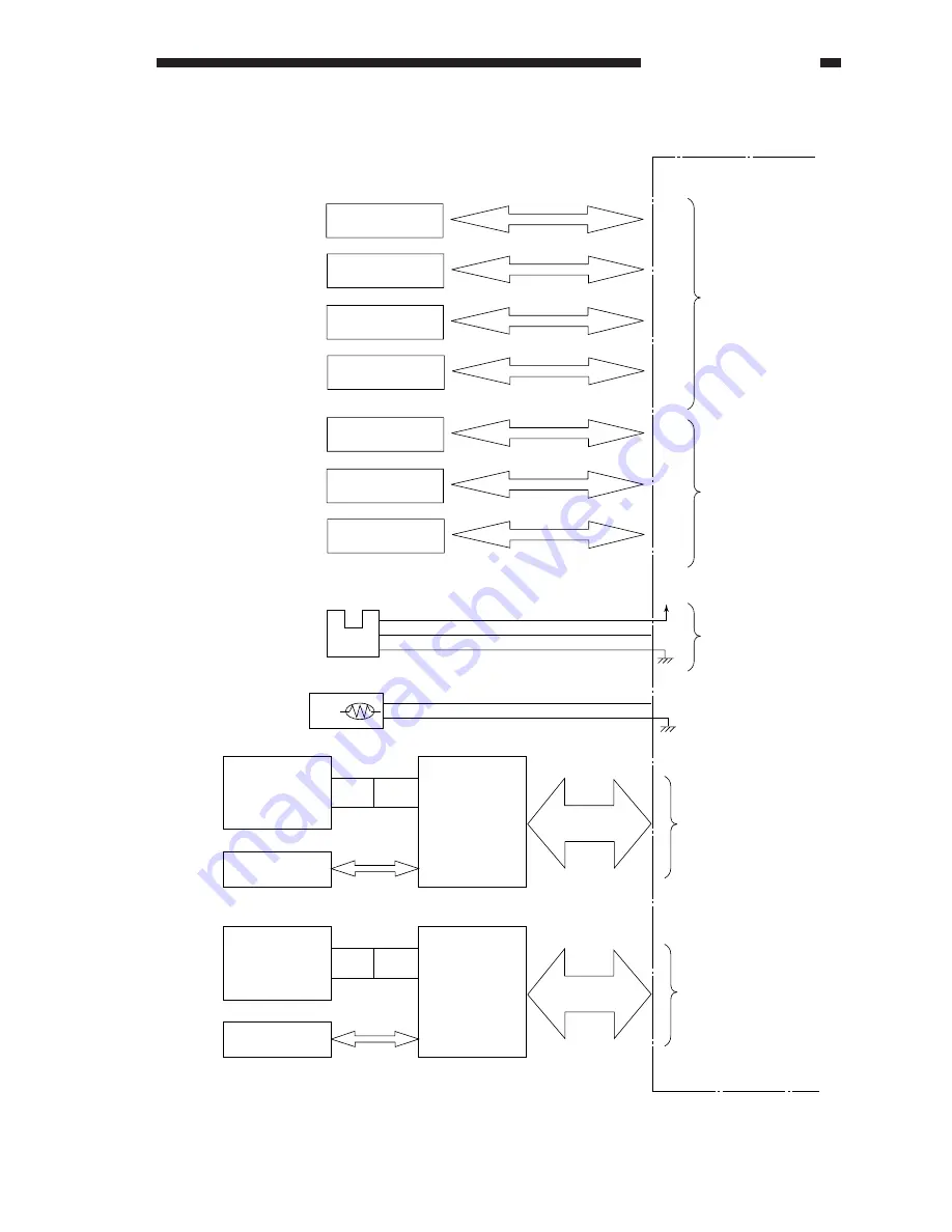
Inputs to the DC Controller PCB (8/8)
Figure 3-113
DC controller PCB
Image position
correction PCB
(front)
CCD front PCB
for pattern reading
LED front PCB
for pattern reading
J 2851F
J 2901F
J 2853F
J 2951F
J 2854F
J 2203
CCD rear PCB
for pattern reading
LED rear PCB
for pattern reading
J 2851R
J 2901R
J 2853F
J 2951R
J 2854R
J 2204
See Chapter 3.
(laser exposure)
See Chapter 3.
(laser exposure)
SALT Y
SALT M
SALT C
SALT K
ATR Y
ATR M
ATR C
J 6099M
J 6099Y
J 6099C
J 6099K
J 2228A
J 2228A
J 2228B
J 2228B
J 6158Y
J 6158M
J 6158C
J 2229A
J 2229A
J 2229B
SALT sensor (Y)
Color toner density sensor (Y)
Color toner density sensor (M)
Color toner density sensor (C)
SALT sensor (M)
SALT sensor (C)
SALT sensor (K)
See Chapter 3.
(image formation)
See Chapter 3.
(image formation)
J 2209A
5 V
OEP*
See Chapter 3.
(feeding system)
Fixing oil level sensor
-12
-13
-14
THM3
THM3
J 2208B - 4
- 5
J 6038- 2
- 1
Image position
correction PCB
(rear)
Polygon scanner
assembly thermistor
PS 6
Summary of Contents for 1000S
Page 12: ......
Page 30: ......
Page 44: ......
Page 86: ......
Page 254: ......
Page 372: ......
Page 374: ......
Page 418: ......
Page 438: ......
Page 442: ......
Page 754: ......
Page 764: ......
Page 766: ......
Page 840: ...0501GR PRINTED IN JAPAN IMPRIME AU JAPON This publication is printed on 100 reprocessed paper ...


