
Installation
Connecting to a Network
Maintenance
Appendix
Index
Appendix
Installation Manual
Projecting an Image
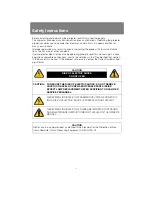
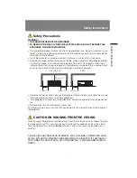
Safety Instructions
Before Use
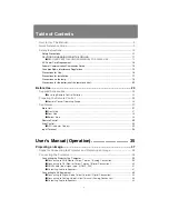
Table of Contents
Setting Functions from Menus
Useful Functions Available
During a Presentation
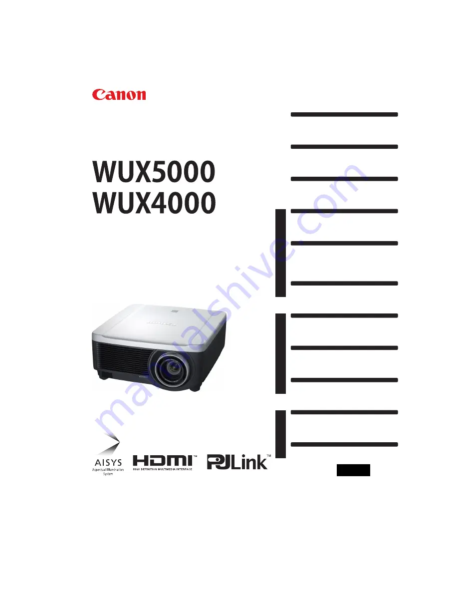
User’s Manual
ENG
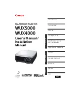
MULTIMEDIA PROJECTOR
User’s Manual /
Installation
Manual
Summary of Contents for 1293B002AA/006AA - Lcos Xga Projector
Page 35: ...35 MULTIMEDIA PROJECTOR User s Manual Operation ...
Page 36: ...36 ...
Page 72: ...72 ...
Page 112: ...112 ...
Page 130: ...130 ...
Page 156: ...156 ...
Page 165: ...165 MULTIMEDIA PROJECTOR Appendix ...
Page 166: ...166 ...
Page 181: ...181 Product Specifications Appendix Other Information ...


